|
GOLIATH / Spectrometer |

|
 |
|
 |
CERN
|
SY
|
SY-EPC
|
HOME
|
CERN
|
SY
|
SY-EPC
|
HOME

|
|
| |||||||||||||||||||||||||||||
| GOLIATH | |
| NR31-01 // NR31-05 | ALGE |
| Power In | 3 ~ 400V/1775A x2 |
| Power Out | 5000A/355V |
| Converter Type | Thyristors 12P |
| Control type | Front end VME |
| DAVID | |
| NR31-06 | ALGE |
| Power In | 3 ~ 400V/1775A |
| Power Out | 2500A/355V |
| Converter Type | Thyristors 12P |
| Control type | Front end VME |
 Operation Responsibles
| 1st Intervention |  Piquet SY-EPC Experimental Areas(163668) Piquet SY-EPC Experimental Areas(163668)
|
| Responsibles: | Yves GAILLARD |
| Xavier GENILLON |
Power Converter Architecture
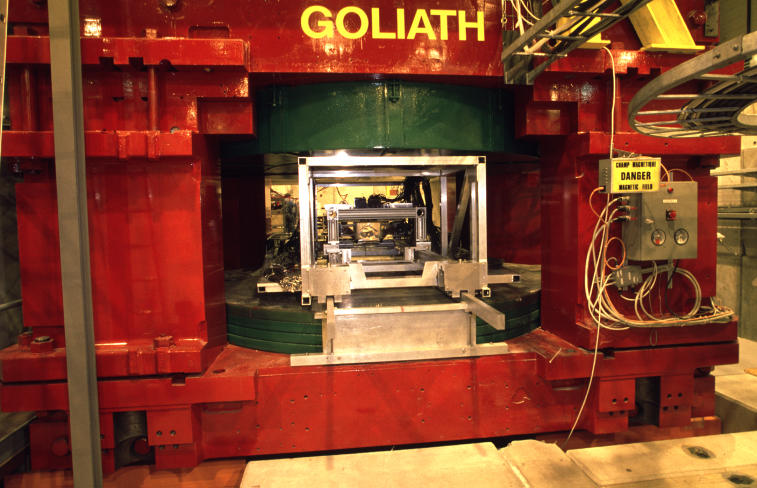
GOLIATH magnet is located on H4 beam line inside PPE134 zone.
This magnet is composed of 2 coils mounted in serie. GOLIATH power converter (NR31-01 // NR31-05) supplies the two coils. DAVID (NR31-06) supplies the bottom coil via a diode installed before the polarity switch.
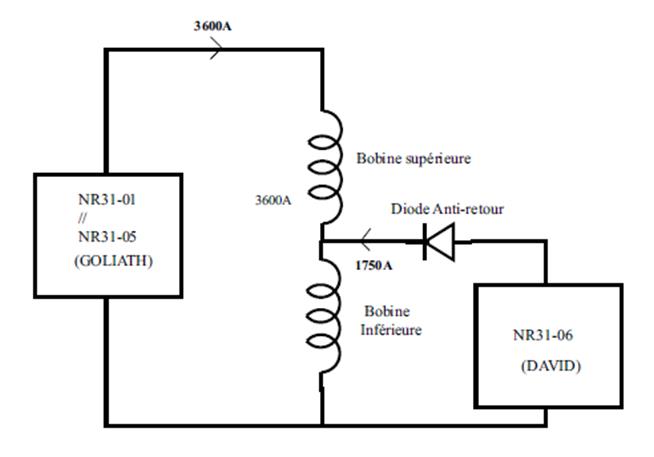
Goliath power converter architecture
Power Part
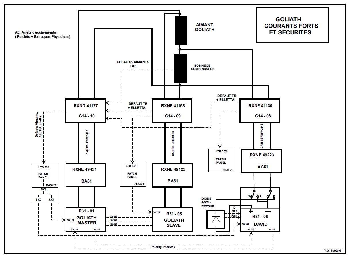
GOLIATH magnet is supplied by 3 R31 power converters.
Particularities:
A electronic card called 'Polarity Interlock' has been added in the supply crate of the NR31-01 and NR31-06 to check the polarity of the 3 power converters.
The control circuit of the MCB Selpact 2000A has been modified.
Control & Regulation Part
CESAR Software (CESAR GUI will not work with Java higher than 1.6.0_18) is used to control GOLIATH power converters.
A special CESAR GUI called "Goliath & David control" is used to send STARTUP or STOP sequence to the power converters.
The STARTUP sequence objective is to start GOLIATH before DAVID and vice versa the STOP sequence will stop DAVID before GOLIATH.
The regulation part is standard.
A current RATE LIMITER card is installed in the converter crate.
Magnet Protection
Magnet faults are sent to BA81 by LTB231 and are dispatched to DAVID and GOLIATH power converters via a relay crate installed in the patch panel RA3422.
Terminal Box (TB) and Cooling Cables interlocks have been connected in serie inside the TB of gallery 14.
Unlike standard power converters the interlock RHEOSTAT is used.
Magnet connection
Goliath Magnet connection simplified schematic
Magnet Types
Superior coil (Copper) + DC Cables: R= 0.043 ohm
Inferior coil (Aluminium) + DC Cables: R= 0.035 ohm
Machine Installation
- 890 (BA81): 3
Goliath power converters are installed in North area:
Production Contract & Contract History
- Manufacturer: ALGE
- Production year: 1976