|
VERTEX / Spectrometer |

|
 |
|
 |
CERN
|
SY
|
SY-EPC
|
HOME
|
CERN
|
SY
|
SY-EPC
|
HOME

|
|
| |||||||||||||||||||||
| RPHGE.887.VERTEX1 | KEMPOWER |
| RPHGD.887.VERTEX2 | KEMPOWER |
| Power In | 3 ~ 400V/100A |
| Power Out | 6000A/8V |
| Converter Type | Switch mode |
| Control type | FGC3 |
 Operation Responsibles
| 1st Intervention |  Piquet SY-EPC Experimental Areas(163668) Piquet SY-EPC Experimental Areas(163668)
|
| Responsibles: | Xavier GENILLON |
| Yves GAILLARD | CERN SY-EPC-LPC |
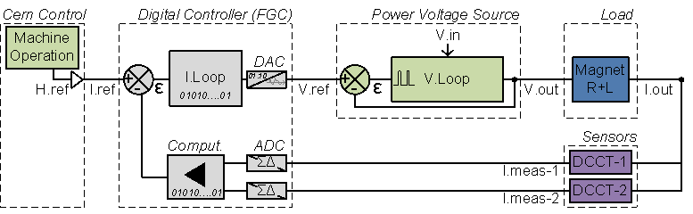
Power Converter Architecture
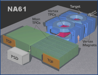
VERTEX magnets 1&2 are located on H2 beam line in EHN1 zone. Each magnet is supplied by a power converter 6kA/8V
The power Converters are integrated in a housing rack, with 3 main parts:
- High Precision Current sensors: DCCTs, able to measure DC current at the required precision.
- Power Part: Power Rack and its removable Power Module
- A Digital Controller (FGC) using WorldFip bus in charge of:
- The high level control from and to the Cern Control Room
- The high precision digital current loop
- Collecting and reporting all status, faults, and measurements from all the different parts to the remote services, for diagnostic and operation purposes.

VERTEX power converter architecture
Power Part
A high current high frequency (25 kHz) switch mode power converter, designed for powering of superconducting loads requiring only positive current and positive voltage control (1 quadrant). Constructed from a modular architecture composed of 2kA power modules, the system can be easily adapted to suit specific powering requirements. Used extensively in the LHC particle accelerator. The converter is water cooled, and is thus ideally suited to situations where air losses must be carefully managed. Designed for underground operation, extensive remote diagnostics have been foreseen to allow efficient monitoring and fault diagnostics without requiring being present locally. Additionnal free wheeling diodes located in the Power Rack always provide a current path, independent of the converter status. Power Converter is normally assembled using a n+1 Power Bricks [+2kA +08V] to provide active redundancy in case of one subconverter is lost. For example, a [+6kA +08V] is composed of 4x [+2kA +08V] Power Brick, working as current source being controlled by a Voltage Source main control.
![[2kA 08V] Sub-Converter simplified Architecture](pagesources/VERTEX powerpart.png)
[2kA 08V] Sub-Converter simplified Architecture
Control & Regulation Part
Control & regulation principles are summarized in a detailled schematics representating only the part involved in the output current regulation scheme.
Regulation Control simplified schematic
High precision current control loop is managed by the digital controller called FGC (Function Generator Controller). This unit includes a high precision Sigma Delta Analog to Digital Converter which digitalize the analog current measurement coming from 2 DCCTs (DC current Transducer). Precision is then directly relying on sensor precision: DCCT, the ADCs, and the algorithm being used for the regulation loop. Voltage source is then used as a power amplifier, powering the load through a high bandwidth voltage loop (>500Hz).
Magnet Protection
Power Converter is part of magnet protection scheme, even if not directly fully responsible of the monitoring and diagnostic of the superconductive magnet status. Dedicated systems QPS (Quench Protection System) + PIC (Power Interlock Controller) can interlock Power Converter if magnet safety requires it.
Power Converter is then expected to:
- Always ensure that external protection system can stop the Power Converter through a safe signal called Fast Abort. This redundant signal uses 2 paths to interlock and stop the converter and its redundancy is checked each time it acts. It directly acts on AC Contactor bobbin, ensuring its opening as required.
- Stop powering the load in safe way (handling the magnet energy even when stopping, through dedicated system called Free Wheeling Diode Safe Paths). This passive system based on different paths using several free-wheeling diodes in the rack provide a safe discharge path for magnet current (energy).
- Monitor Earth current of the total circuit: converter + load (magnet and its DC cables), and take the right action if threshold reached.
Free Wheeling Diode Safe Paths:
The system is based on 3 different paths provided by Free-Wheeling Diodes providing a safe path for magnet current. The number of Free-Wheeling diodes (x40..x80, 20x per cards) to be considered depends on the converter type (see chapter Machine Installation below). Only one unique Additionnal Free-Wheeling Diode is always present as a last chance 3rd path.

Crowbar System simplified schematic
Earth System:
The circuit injects a 100 mA DC current on a grounded resistive branch, resulting in a common mode voltage at the output circuit easing the earthing fault detection. Output circuit Common mode voltage is, without any earth fault, around 10V (=100 mA x 100 Ohms), and is not relying on load operation, making possible to detect an earth fault even with converter being OFF. (OFF, not condamned).
If an earth fault occurs on the output circuit, a faulty current will be deviated from the initial path back to earth by using the shunt 10 Ohms resistor path (monitored for detecting this fault).
Overcurrent protection is achieved through a 1A-100V fast fuse in series in the path provided for the earthing fault current.
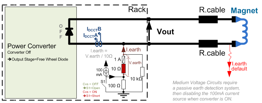
Earthing System simplified schematic
Magnet connection
Energy extraction system:
The EE facilities are composed of three fundamental components: the dump resistors, the switching circuit breakers and the associated control electronics.
The electrical layout of the circuit is shown in Figure below. Two circuit breakers (CB11 and CB12 in the figure) open their contacts in case of power abort request or hardware failure. This isolates the power converter from the circuit, with two possible operational modes to extract the energy from the magnet: - A slow extraction, also called Slow Power Abort (SPA), where the switches CB21 and CB22 stay closed, providing an equivalent resistance in the circuit of 2.67 mohm, which discharges the energy stored in the magnet in approximately 50 minutes; - A fast extraction, Fast Power Abort (FPA), where the switches CB21 and CB22 will open, leaving only the 8 mohm resistance in the circuit, which discharges the energy from the magnet in 17 minutes. In addition, 100 mF capacitances are put across the switches to reduce the arcing during switch opening with current. A set of diodes is installed in series with switches CB21 and CB22, to avoid parasitic currents circulating through this branch in normal operation, when the switches are closed. Because of these diodes, the polarity swap is installed between the two resistor branches (not indicated in Figure for sake of simplicity, but definitely included in the final design). The EE system was developed by TE-MPE and is under its responsibility.
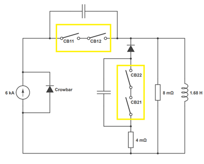
Electrical layout of EE circuit
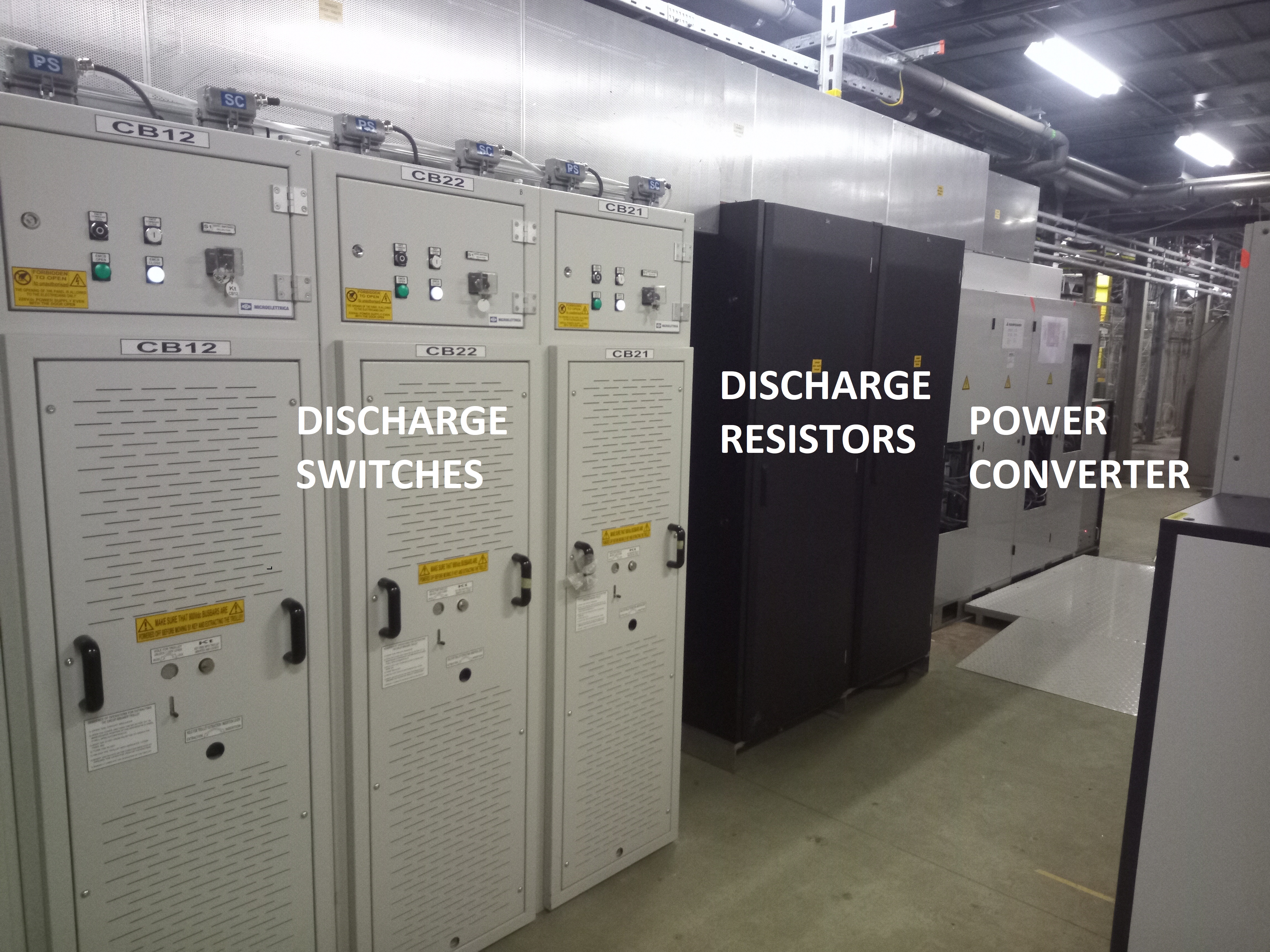
VERTEX 1 power converter and his energy exctraction system
Magnet Types
- Field:1.5T
- Current:5000A
- L: 1.68H
- R: 0.2 mOhm
- Weight:380T
Superconducting Magnet VERTEX 1 (Alsthom) VERTEX 2 (Ansaldo) :
Machine Installation
- LHC 188 Pc
- ATLAS Solenoide 1 Pc
- PS 2 Pc
- NA(EHN1) 2 Pc
This kind of power converter is installed in:
Production Contract & Contract History
- KEMPOWER
- Production year: 2001-2003