 PS Booster accelerator:facts & figures PS Booster accelerator:facts & figures
PS Booster ring was developed in the 60 s (first p+ in 72) to increase injection energy in the PS from 50 to 800 MeV as required by the ever increasing beam intensities.
Since its creation, the PS Booster extraction energy has already been increased twice: 800MeV to 1GeV (1988),1 GeV to 1.4GeV (1999)
Booster Accelerator
Takes particles from Linac2 at 50MeV and accelerates them up to 1.4GeV
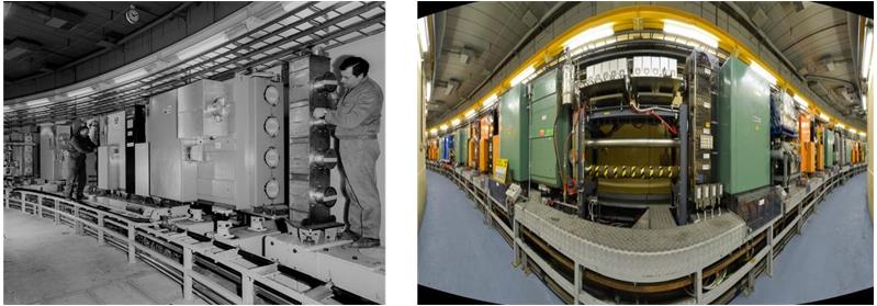
4 rings 157m circumference accelerator. 32 dipoles and 48 quadrupole magnets connected in series.
Booster Magnets:4 magnets into one structure
From 1.4GeV to 2GeV: the rationale
The main limitation to machine performance appears to be connected with tune shift due to space charge.
Increasing beam energy will decrease the factor: 1/βϒ² leading to higher intensity with same maximum |∆Q| (a value around 0.3 seems to be accepted as limit).
Linac4 will increase PS Booster injection energy from 50 to 160MeV (factor of 2 in 1/βϒ² and in p+ density).
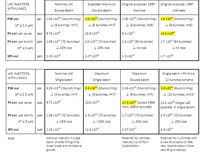
The improved performance related to Linac4 can only be exploited only lifting the space charge limit in the PS. This is achieved by increasing the injection energy in the PS.
Mainly for Magnet limitations (max current), it is not possible to recover the same factor of 2 given by the Linac4. With 30% magnetic field increase (10% Irms increase) a factor 1.6 can be achieved.
Present MPS limitations
The present power converter is composed of 4X12 pulse thyristor bridges directly connected to the AC network via a 3 winding 18kV/389V transformer.
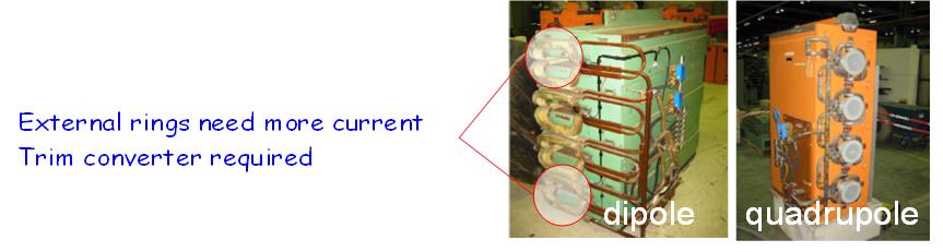
Trims converters are needed for external dipole rings and for quadrupoles
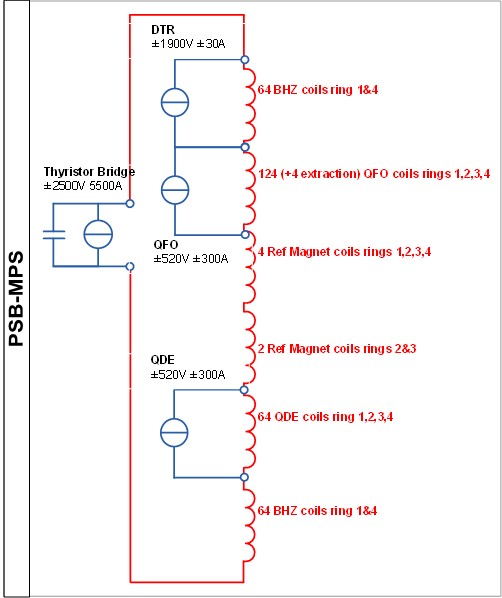
Layout present MPS
Limitations:
The performance is limited to 3.6kV x 4kA peak power on the magnets.
Due to Udc voltage limitation, 2GeV cycle would be too slow. To high rms for converters and for magnets
Rms current in transformers already close to the limits.
Reactive power (and Active peak power) drawn from the 18kV network already at limit.
18kV network quality at risk due to further increase in power peak
The PSB-MPS is not suited to provide the voltage and current profiles required by the increased extraction energy from 1.4 GeV to 2 GeV
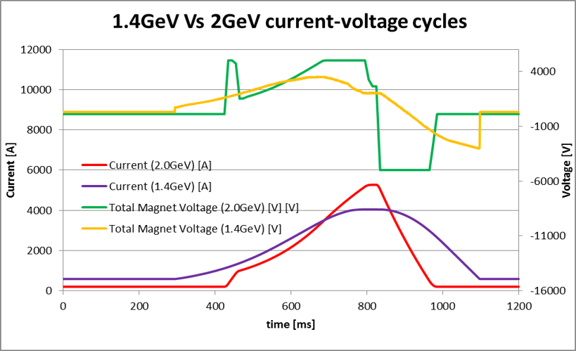
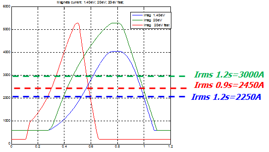
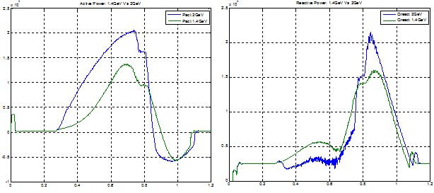
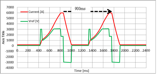
Voltage and current profiles
POPS-B power converter
P+ energy increased from 1.4 to 2GeV. Current increased from 4 to 5.5kA.
Magnets will be split into 2 equivalent series
2 separated power converters will be used to power each half string of magnets
Only 2 trim converters required for quadrupoles
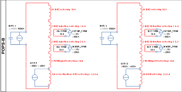
Layout new POPSB
The project includes the following working units:
- Construction of a new building to host the new MPS
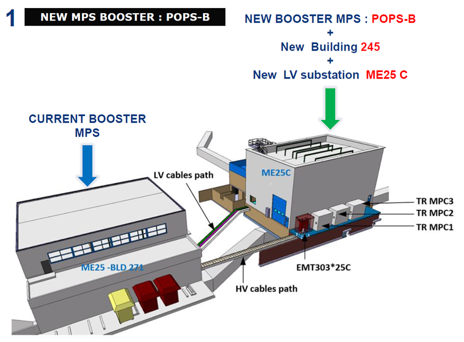
245 and 271 buildings
- Realization of the MPS high power converters
- Realization of the quadrupole trims (+ injector and extraction trims)
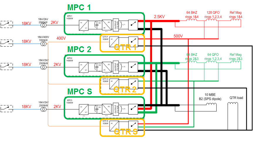
power converters overview
1 MPC based on IGBT/IGCT technology and energy storage principle.
1 QTR for trimming the current in quadrupoles
Identical structure repeated three times: two for the magnet strings and one for spare
Magnets Upgrade (Courtesy A. Newborough)
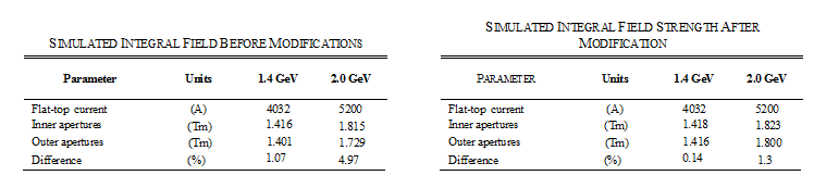
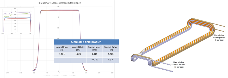
Operation at 2GeV increases the saturation of outer magnetic circuits, thus enhancing the difference between inner ant outer coils. To correct this a substantial current trim must be allowed in outer ring with respect to inners.
QFO trims must be severely over-dimensioned to compensate this effect.
Magnet upgrade.
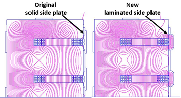
The addition of the laminated side plates on the four aperture PSB dipole magnet allow the increase of extraction energy from 1.4 to 2.0 GeV energy without further increasing the difference between the inner and outer apertures.
- Injection/Extraction dipoles:
Why do we need a new Ref magnet to operate at 2GeV ?
Due to the different coil configuration to allow space for the INJ and EXT vacuum chambers, there is a slight difference in field to that of the normal magnets
As we will install the laminated side plates on the normal magnets but not the special magnets, we must compensate for this with the new PC
Injection/Extraction dipoles.
Why do we need additional trim converters for special Injection and Extraction dipoles ?
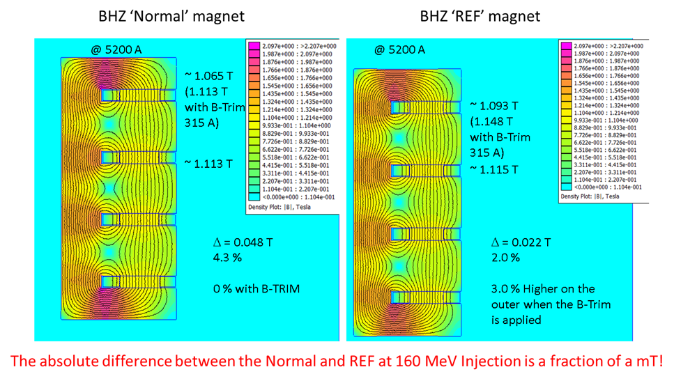
Reference magnet.
POPS-B design
- Performance requirements:
New 2GeV cycle requires 47% higher (total) voltage, 25% higher peak current and 10% higher rms current.
Current and voltage profiles for dimensioning of the single POPS-B power converter.
Voltage measurements on present cycle flat-top gives 10Vpk ripple mainly at 300Hz and 600Hz.
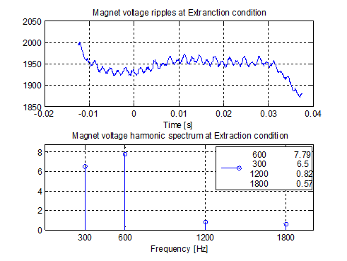
MPS voltage ripple
For each string this translates into a requirement of DV < 3.5Vrms. 2.5Vrms would give additional improvement
A storage capacitor bank connected on the DC side provide power decoupling from the network. The storage capacitance is around 0.3F (@5kV Udc nominal)
| Power transformer: |
Power=2.5MW,Vac=2000Vrms |
| Storage Capacitors: |
Cap=0.3F, Vmax=5000V, Vmin=3000V |
| Output: |
Imag_pk=6000A, Imag_rms=3000A, Vout_pk=3000V |
| Load (Mag): |
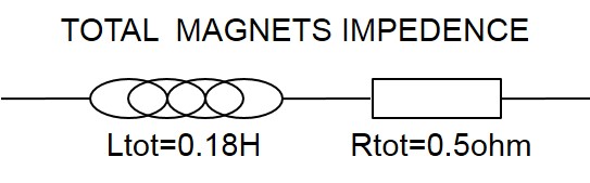
Lmag=100mH, Rmag=250mOhm |
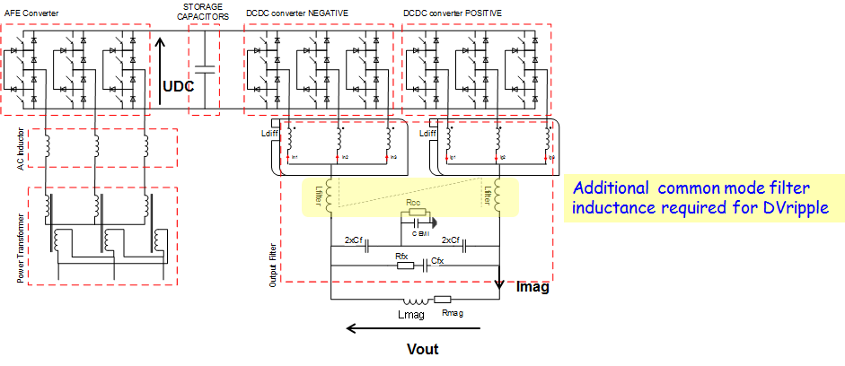
Power topology.
Project Planning
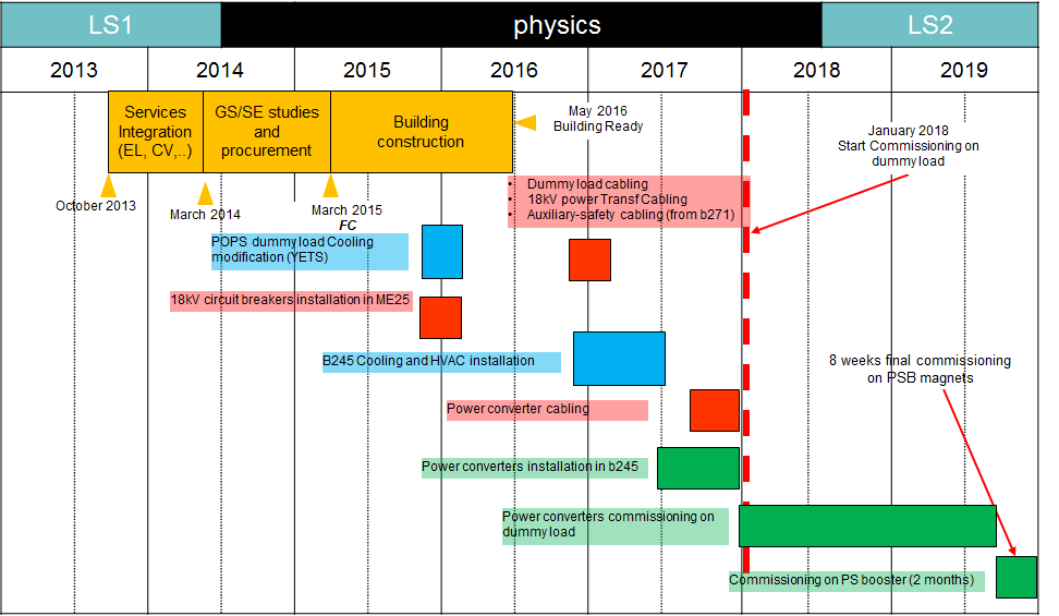
Planning total.
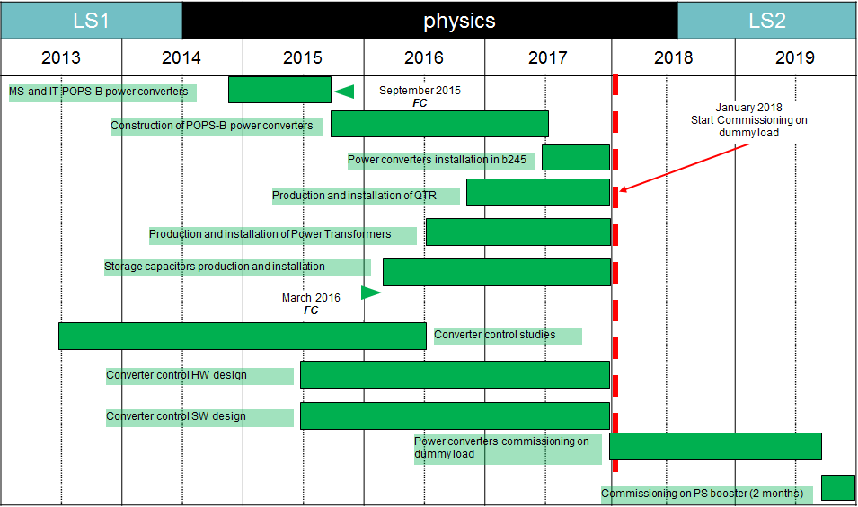
Planning POPS-B Power converter.
| 
 |
|
 |
CERN
|
SY
|
SY-EPC
|
HOME
|
CERN
|
SY
|
SY-EPC
|
HOME
