|
Capacitor Test Bed / CERN |

|
 |
|
 |
CERN
|
SY
|
SY-EPC
|
HOME
|
CERN
|
SY
|
SY-EPC
|
HOME

|
|
| |||||||||||||||||||||||||||||||||||||||
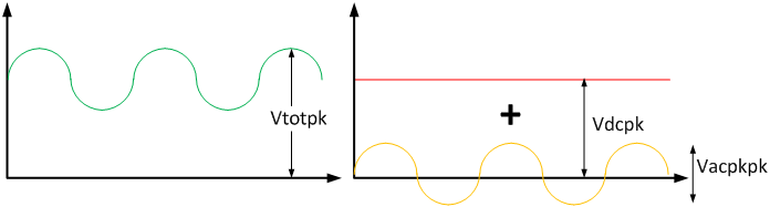
| Vdcpk | 5500V |
| Vacpkpk | 4000V |
| Vtotpk | 7500V |
 Operation Responsibles
| Responsibles: |
|
|
|
|
|
|
Power Converter Architecture
This composite voltage is meant to supply a load constituted by a set of capacitors.
The capacitance value changes depending upon the test to be effectuated, with a maximum rms current fixed in 80Arms.
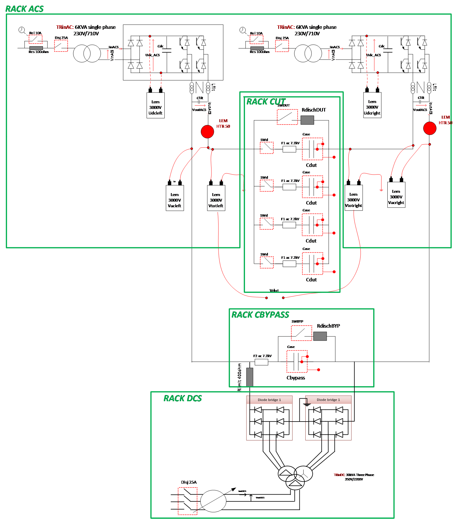
Power converter architecture
Power Part
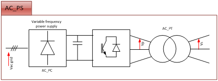
The AC source:
The AC source is the most demanding in term of power. In-fact it has to provide all the kVAr needed by the tested capacitors.
The worst conditions are met when the testing of the fully sized element is required. To keep a limit, lets consider the present capacitor value of 2mF; the following calculations give us the power needed:

| Pac3ph | 500kVA |
| Vacgrid | 400V |
| Vpll | 400Vrms(line2line) |
| Ip | 720Arms |
| Vsll | 1850Vrms |
| Is | 160Arms |
The DC source:
The simplest DC source is a 3 phase diode bridge. For easier realization (and to keep compatibility with other testing requirements), a 12 pulse diode bridge is foreseen.
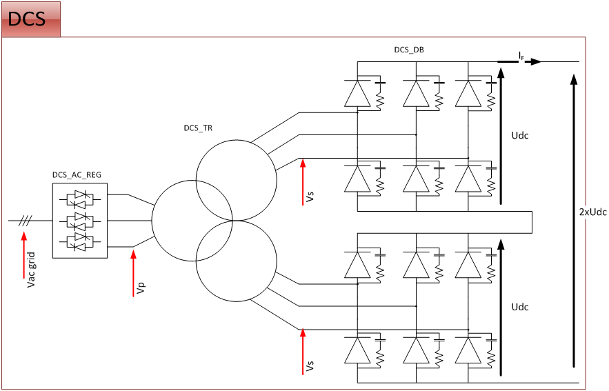
Two 6 pulses diode rectifiers are then connected in series.
The following values have to be considered for bridge sizing:
| Udc= | 100/2800V |
| Vsll | 2000Vrms (line2line) |
| Is | 10Arms |
| As | 34kVA |
| Vpll | 400Vrms |
| Ip | 100Arms |
| Ap | 68kVA |
Control & Regulation Part
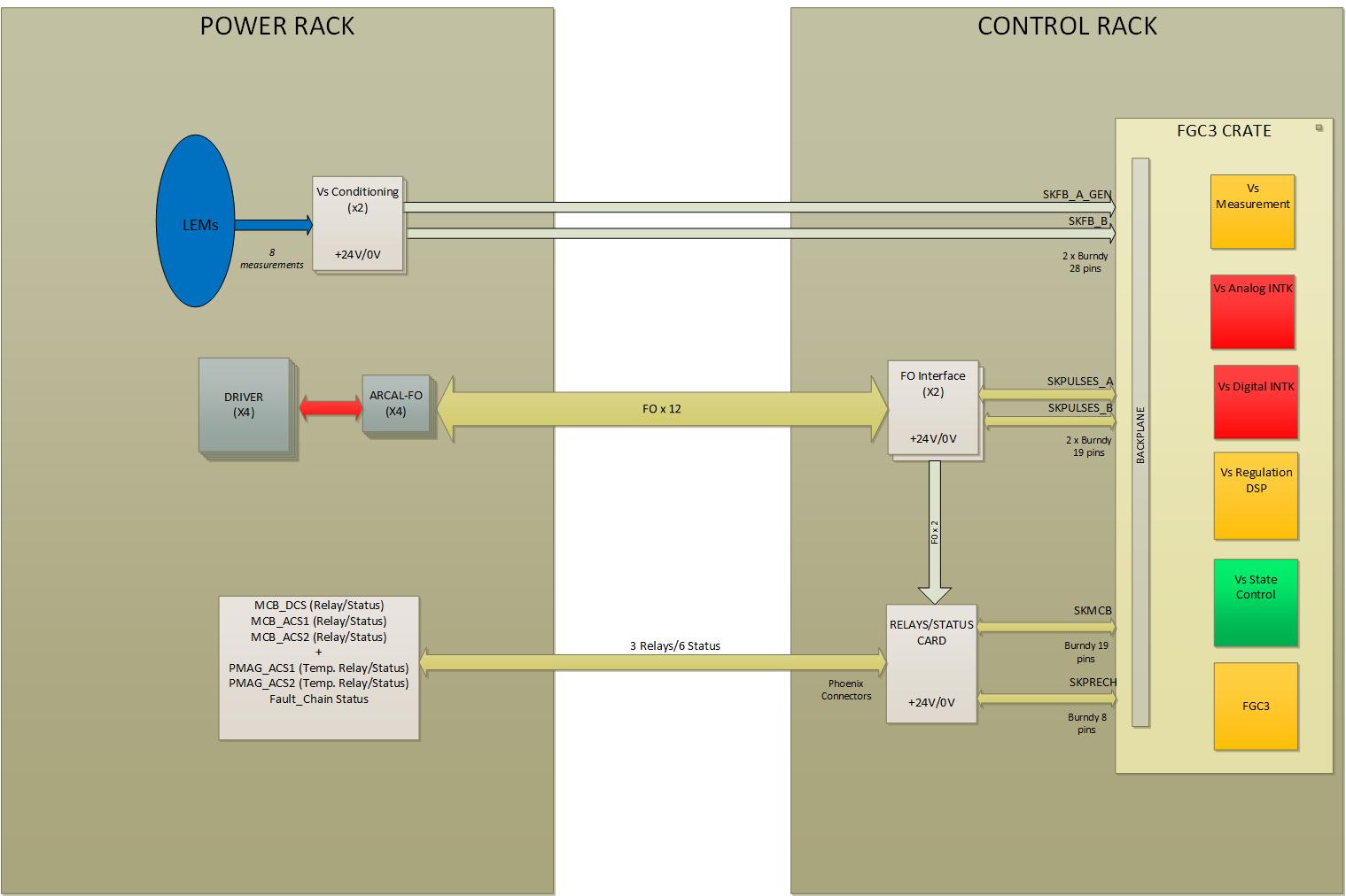
Control overview simplified schematic