|
SMD / SPS Mains Dipole |

|
 |
|
 |
CERN
|
SY
|
SY-EPC
|
HOME
|
CERN
|
SY
|
SY-EPC
|
HOME

|
|
| |||||||||||||||||||||||||
| RPPAF | SIEMENS GMBH |
| Power In | 3 ~ 18KV/450V 2.56 MVA |
| Power Out | 5.9KA/2100V |
| Converter Type | Thyristors 12P |
| Control type | FGCD(MUGEF) + SPS Analogue electronics type B |
 Operation Responsibles
| 1st Intervention |  Piquet SY-EPC Experimental Areas(163668) Piquet SY-EPC Experimental Areas(163668)
|
| Responsibles: | Olivier MICHELS |
| Charles GENTON | |
| Isaac CROSS |
Power Converter Architecture
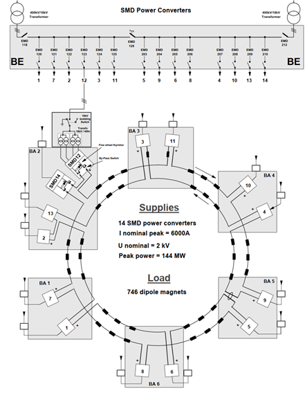
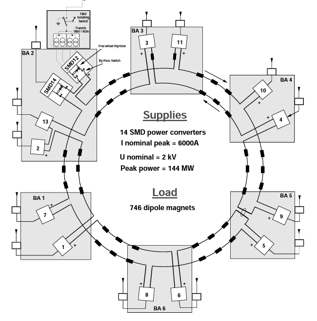
The SPS Main Dipole converters (also known as SMDs) consist of 14 thyristor rectifier stations, of 12 MW each. The SPS accelerator requires 12 of these stations (=144 MW) operating in series with the main dipole magnets. The remaining 2 stations are available as spare converters, and can replace a faulty converters by configuring a set of DC switches, managed remotely by a PLC (CIS Control and Interlock System for the SPS Main Power Converters).
Each power converter circuit is composed of a main circuit breaker (MCB), a manual 18 kV isolating switch (with ground), two 18 kV/450 V transformers, and a remotely operated by-pass switch (connection or disconnection to the magnets). The power converters are located in six buildings: BA1, BA2, BA3, BA4, BA5 and BA6. The main circuit breakers and the general circuit breakers (EMD118 and EMD212) are located in the BE building next to the substation.
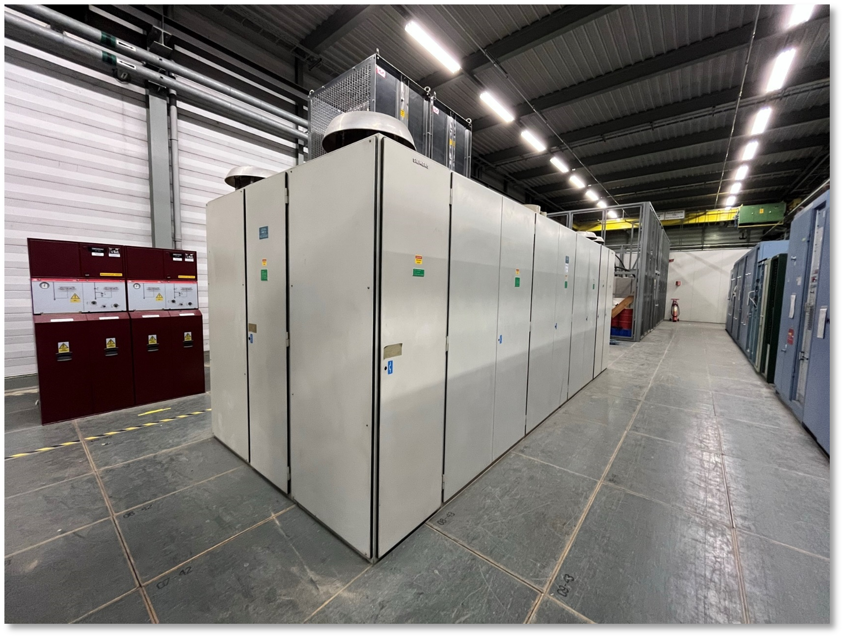
SMD converter architecture
Power Part
| Power In | 3 ~ 18KV/450V 2.56 MVA |
| Power Out | 5.9KA/2.1KV |
| Cooling type | Demineralized water |
The rectifying stage of one SMD converter consists of 4 thyristor bridges, supplied individually by a 2.56 MVA transformer, stepping down the AC voltages from 18 kV to 450 V. Among the four thyristor bridges, two 12-pulse converters are created by phase-shifting their respective two transformers secondaries by 30 degrees. The two 12-pulse converter outputs are connected in series to reach an output DC voltage of ~ 2 kV. The output stage of the converter stations is a passively damped filter, complemented with an active filter. The active filter is driven by a control signal generated by the voltage controller
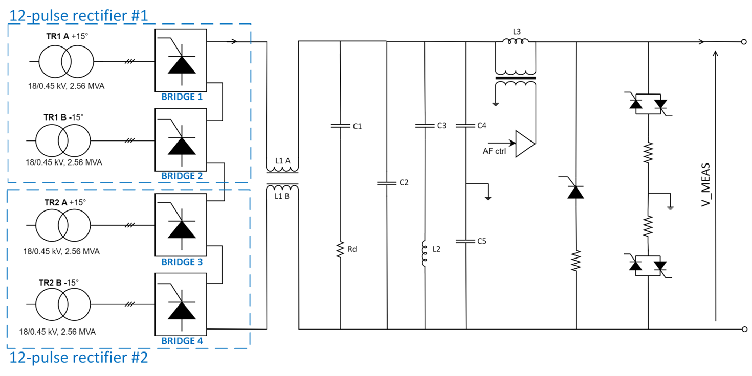
Power layout of one SMD station
The resulting output current and voltage of the 12 SMDs operating together are 6 kA/25 kV. Typical SMDs current and voltage during an SPS super cycle are presented in Figure below.
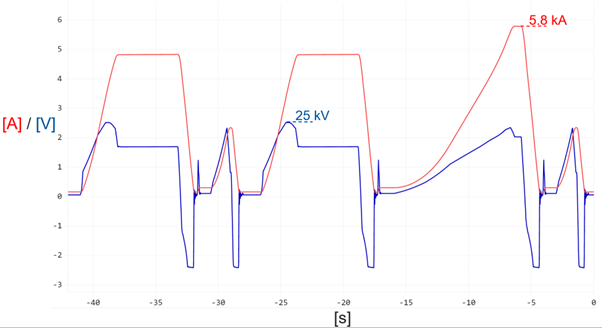
Typical output current and voltage of the SPS main dipoles during an SPS super cycle
Control & Regulation Part
Each individual station manages locally voltage regulation and firing, following a voltage reference distributed around the SPS ring, from a common current controller. The voltage regulation and firing are currently implemented in analogue electronic crates, commissioned in the 70s.
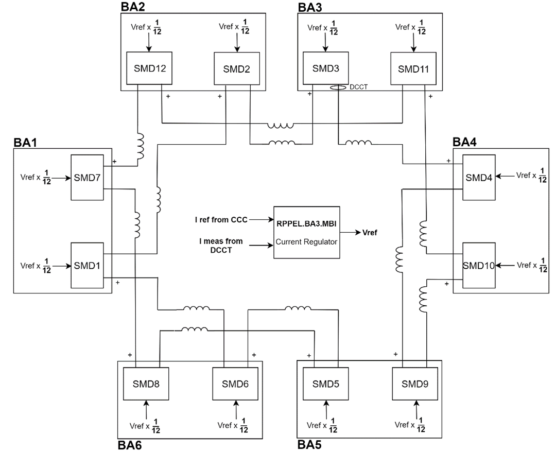
SPS main dipoles current regulation principle
The SPS main power converters are part of one same large power system, with several control layers, protection layers and interfaces.
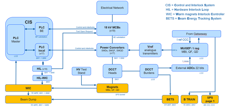
SPS MPS contol layers
The CIS (Control and Interlock System) is in charge of the protection, control and supervision of the main power converters of the SPS. The system is based on a technical infrastructure implemented with Programmable Logic Controllers (PLC). The CIS is a state of the art industrial control system, with S7-1500 PLCs running standard UNICOS-CPC code, developed in TIA portal with its improved diagnostics capabilities, connected to WinCC-OA supervision system based on UNICOS framework, modern and usable local HMIs touch panels.
In case of an outage of one SMD or SMQ converter, the CIS can remotely replace the faulty converter by a spare one, by controlling the bypass switches located between each power converter and the magnets.
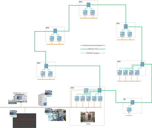
Control architecture of the new CIS
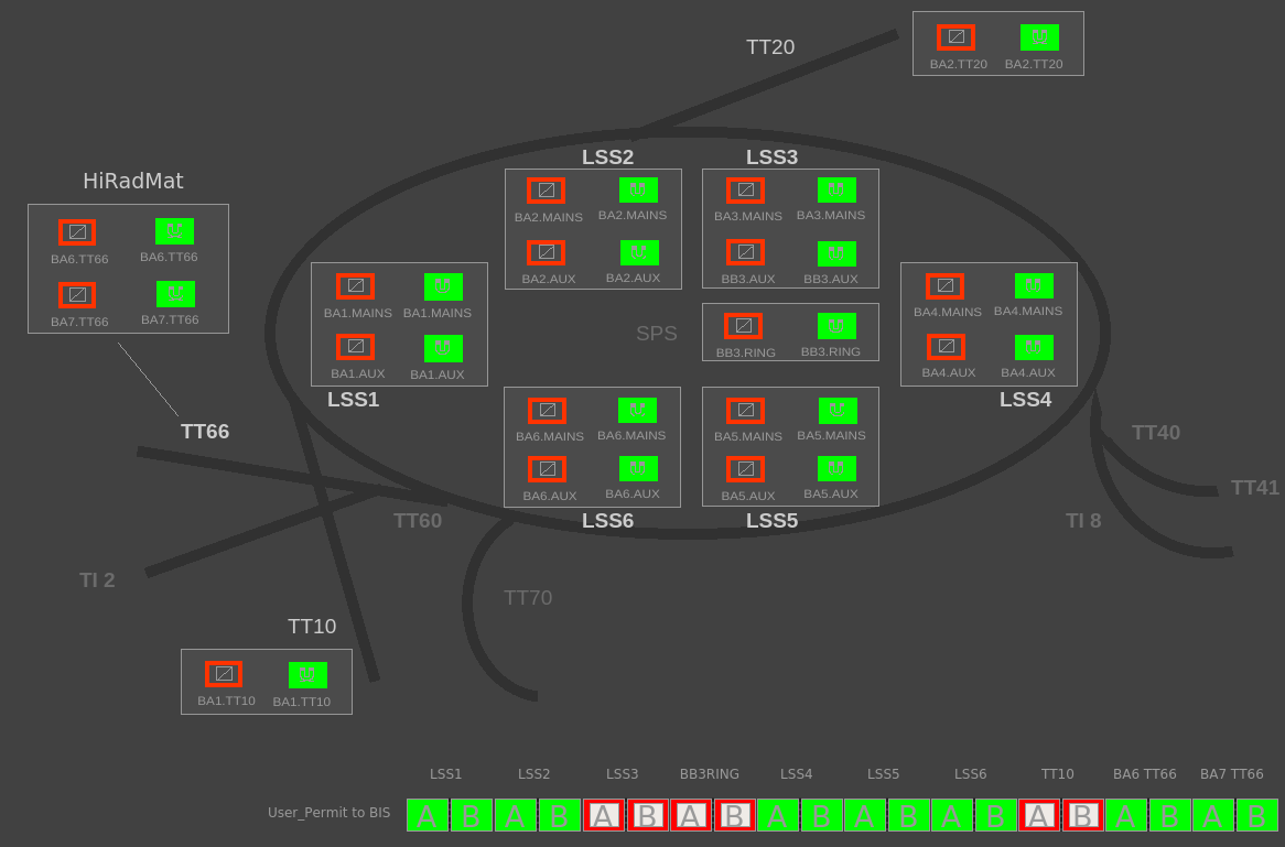
A second control and protection layer exists, providing fast propagation of trip orders in case of failure of one converter. This chain is called the Hardware Interlock Loop (HIL), and it consists of a current loop circulating through optocouplers.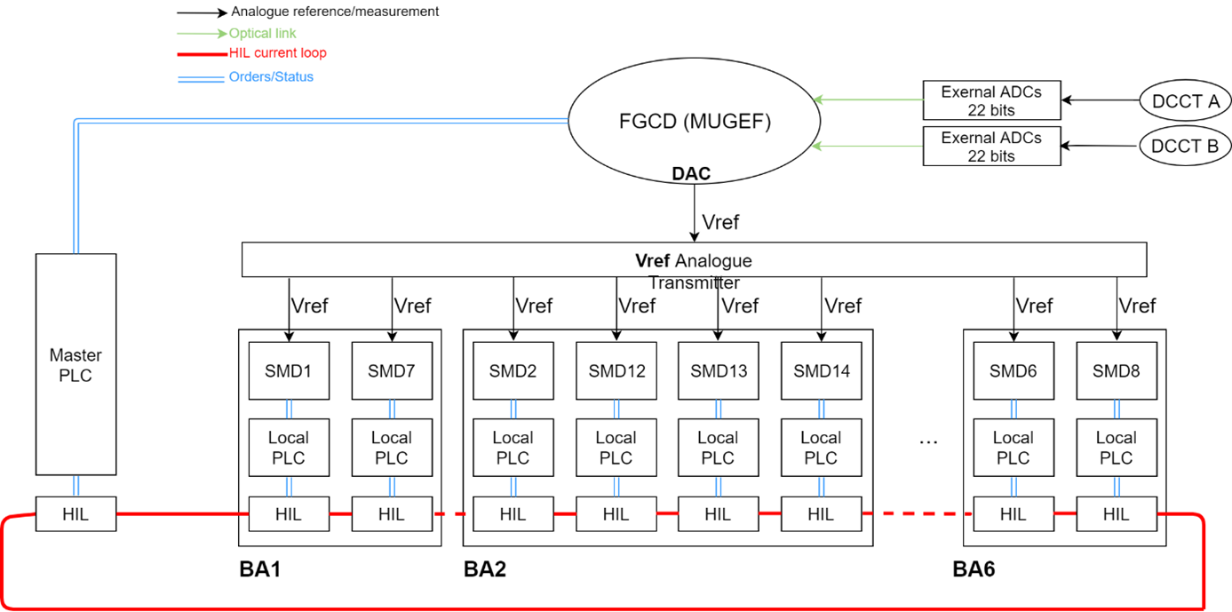
SMD HIL
The supervision application has been developed at CERN using the technologie WinCC-OA-UNICOS.Many views were developed for the operation and diagnostic.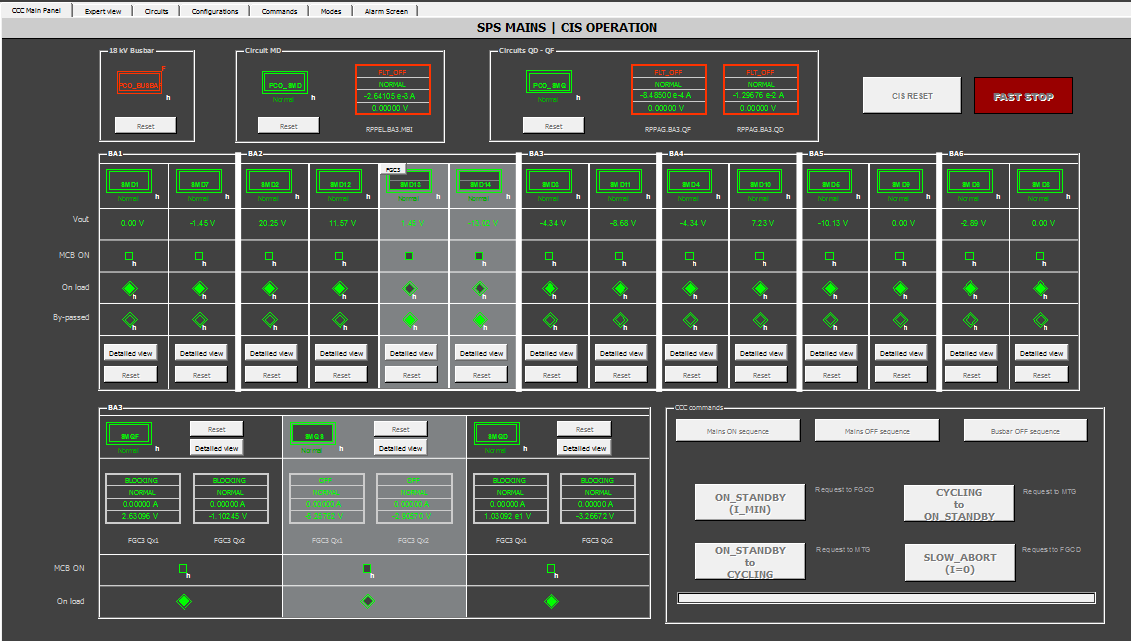
CIS HMI view
Magnet Protection
The dipole magnets of the SPS magnets are protected by a WIC (Warm Interlock Controller) system .
The WIC is a Programmable Logic Controller (PLC) based system. It protects the normal conducting magnets from overheating by switching off the power converter when a fault occurs.
WIC view
Magnet connection
- Dipole Magnets:In the SPS there are 744 main dipole magnets (124 per sextant) divided in two families of different aperture: MBA and MBB. + 2 reference dipoles in BA3 for B-train
- L ~ 6.3 H
- R ~ 3.3 Ohms
- Interconnections:
- Interconnections between magnets in tunnel with water cooled copper busbars (supplies both power and cooling)
- Interconnections between converters (surface) and magnets (tunnel) with water cooled cables (2 per polarity)
- 2 busbar with current circulating in opposite direction to minimize stray field; each one connected every two dipoles
- Delta-I: interlock monitoring current balancing in BA5 (surface)
SPS Dipole circuit connection
Magnet Types
- Dipole magnets:
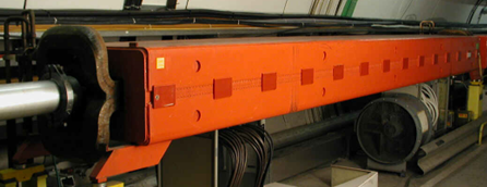
SPS Dipole magnet.
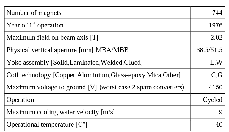
SPS Dipole magnet characteristics.
Machine Installation
Production Contract & Contract History
- Manufacturer: SIEMENS
- Production year: 1976