|
S21 / CERN |

|
 |
|
 |
CERN
|
SY
|
SY-EPC
|
HOME
|
CERN
|
SY
|
SY-EPC
|
HOME

|
|
| |||||||||||||||||||||||||||||||
| S21 | CERN |
| Power In | 3 ~ 400V/126A |
| Power Out | 7000A/9V |
| Converter Type | Thyristors 6P Gradator |
| Control type | Local windows machine |
 Operation Responsibles
| 1st Intervention |  Piquet SY-EPC Experimental Areas(163668) Piquet SY-EPC Experimental Areas(163668)
|
| Responsibles: |
|
|
|
Power Converter Architecture
The S21 Power Converter is used in EHN1 experimental hall to power supraconducting magnets, for DC application called ATLAS Morpugo and VERTEX1&2.
These power converters are composed of 3 main parts:
The Power part contains the 400V contactor, the thyristor gradator, the transformer, the diode bridges and auxiliary circuitry.
The control electronics is integrated in a control rack installed close to the Power Converter. Its function is to provide the local interface between the Power part and the Control part. There is no standard converter crate installed, the control electronics is a LEP electronics type which has been adapted to this power converter. Its function is to achieve with two loops the regulation of the output current and voltage and interface to a windows machine. The HMI (Human Machine Interface) is a specific Labview software use by the physicists. The CCC cannot control this power converter remotely.
The discharge resistors cubicle installed close to the power converter contains 2 power contactors, diodes and resistors to ensure the magnet discharge and also a manual polarty switch.
S21 power converter architecture
Power Part
The power converter topology is a association of a voltage dimmer with a star/star transformer and a diode bridge.
Connected to the 400V network the thyristors dimmer varies the voltage to the primary of the transformer. The secondary voltages of the transformer are rectified by a diode bridge.
The continuous output voltage setting is obtained by the variation of the voltage at the transformer primary.
| Power In | 3 ~ 400V/126A |
| Power Out | 7000A/9V |
| Cooling type | Demineralized water |
| Converter Weight | ? |
| Converter Size | width: 1300mm |
| depth: 1100mm | |
| height: 2000mm |
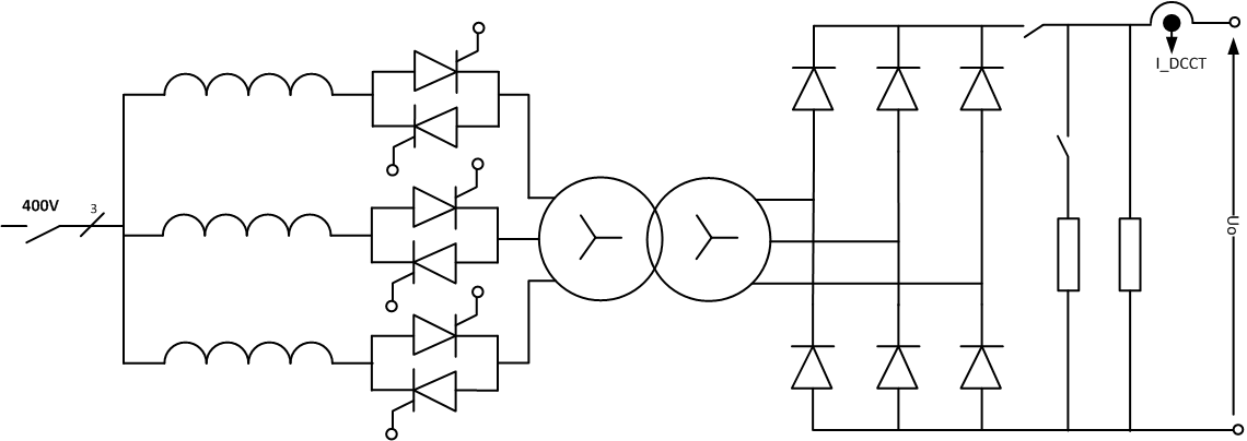
Power Part simplified Architecture / Topology .pdf
Control & Regulation Part
Control: The S21 power converters are not connected to the standard control system of the north area. These equipments are controlled localy by the users from the physicist barrack or from a FALCO terminal by the power converter specialist. The CCC cannot control it remotely.
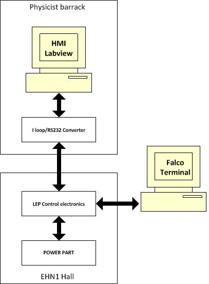
S21 Control system simplified schematic
HMI Labview software used to control S21 power converters:

Regulation: Regulation of the output current is achieved with one current loop which ensures stabilisation for low frequency perturbations. The current loop is driven by a remote controlled precision reference source (DAC). A precision current transducer (DCCT) measures the output current and produces a voltage developed across high precision and stability resistors (burden). A precision comparator amplifier with very high gain, compares the DAC and DCCT signals and produces a voltage to drive the firing of the thyristor bridges, which is synchronised with the 50 Hz incoming supply, occurs at a 300 Hz frequency. During operation such as Polarity Switch change and under fault circumstances, the Blocking signal acts directly on the Thyristor trigger drivers to inhibit the output firing circuits.
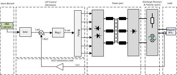
Regulation Control simplified schematic
Magnet Protection
Power Converter is part of magnet protection scheme, even if not directly fully responsible of the monitoring and diagnostic of the superconductive magnet status. The cryogenic dedicated systems can interlock Power Converter if magnet safety requires it. An external energy extraction system handle the magnet energy when a quench is detected or when the voltage in the current leads is too high. These current leads are the electrical conductors located at the transition between cold and warm environment.
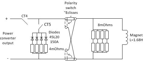
S21 Magnet Discharge System .pdf
Remark: The diodes 45L20/150A are not mounted in Vertex 1 discharge system
Power Converter is then expected to:
- Always ensure that external protection system can stop the Power Converter through two safe signals called Fast Discharge and Slow Discharge.
- Stop powering the load in safe way.
- Monitor Earth current of the total circuit: converter + load (magnet and its DC cables), and take the right action if threshold reached.
Activation of the magnet discharge signals automatically causes the Clamp signal to be generated, causing the Reference Current value to go to zero, followed with the switch off of the power converter Main Circuit Breaker.
Magnet connection
- There are no terminal boxes installed between the power converter and the magnet.
Magnet Types
- ATLAS Morpugo (H8 Beam Line)
- VERTEX 1 & VERTEX 2 (H2 Beam Line)
S21 power converters supplies the following superconducting dipole:
Machine Installation
- 887 (EHN1): 3
Number of S21 power converters installed in North area:
Production Contract & Contract History
- Manufacturer: CERN
- Production year: 1995