|
R11 / BBC |

|
 |
|
 |
CERN
|
SY
|
SY-EPC
|
HOME
|
CERN
|
SY
|
SY-EPC
|
HOME

|
|
| |||||||||||||||||||||||||||||||
| R11 | BBC |
| Power In | 3 ~ 400V/150A |
| Power Out | 500A/150V |
| Converter Type | Thyristors 6P |
| Control type | Front end VME |
 Operation Responsibles
| 1st Intervention |  Piquet SY-EPC Experimental Areas(163668) Piquet SY-EPC Experimental Areas(163668)
|
| Responsibles: | Yves GAILLARD |
| Xavier GENILLON |
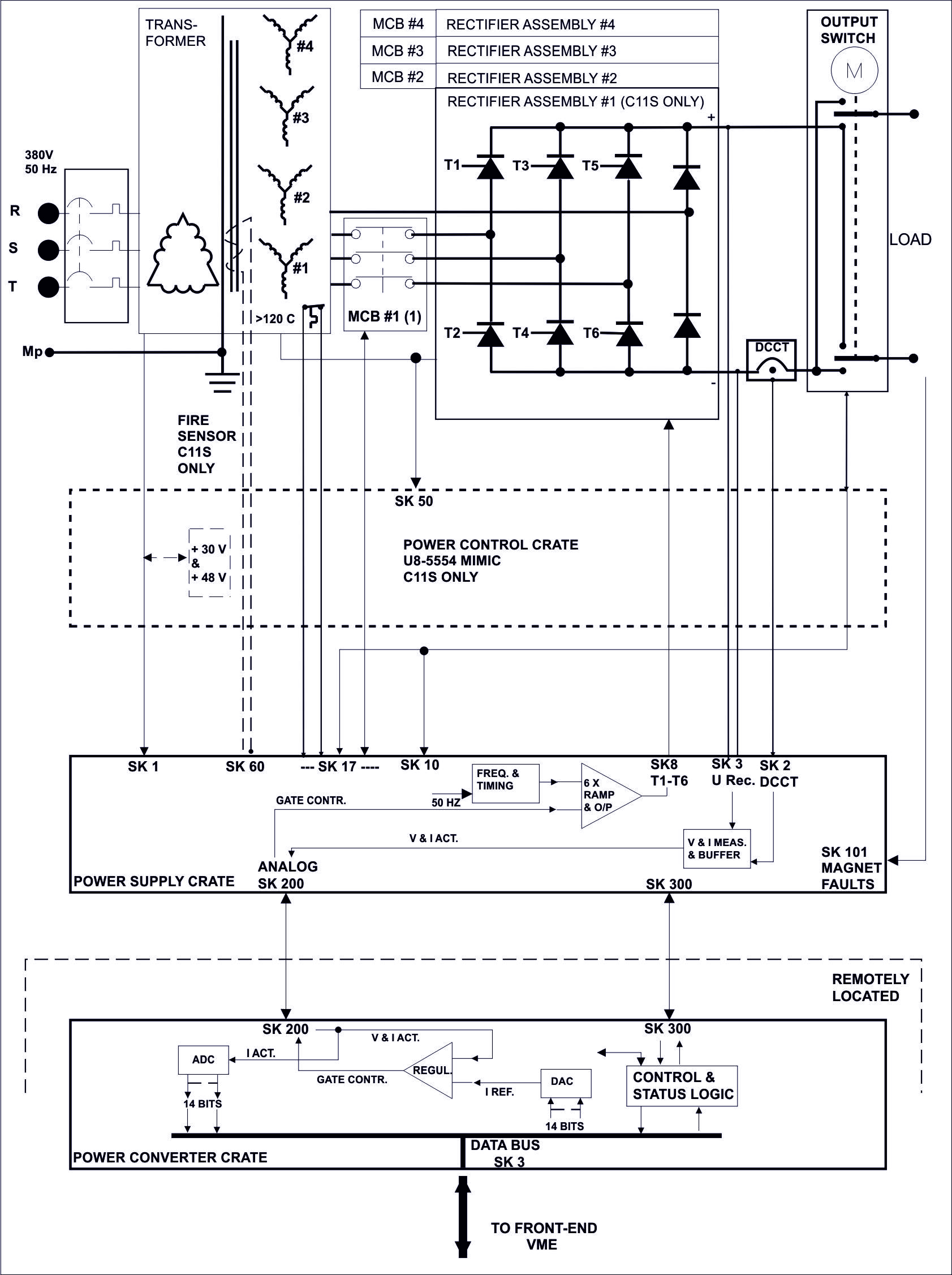
Power Converter Architecture
The R11 Power Converter is used in North experimental area to power mainly the quadrupole magnets, for DC application. It can also supplies correction magnets
This power converter is composed of 3 main parts:
The Power part contains the transformer,the Main Circuit Breaker, the thyristors bridge, the DCCT, the polarity reversal switch and auxiliary circuitry.
The Power Supply Crate is integrated directly in the Power Converter enclosure. Its function is to provide the local interface between the Power Converter and the Converter Crate.
The Converter Crate is remotely located from the rest of the power converter components, in a temperature controlled area, to enhance the stability of the analog circuitry. Its function is to achieve with two loops the regulation of the output current and voltage and interface to a common data bus which is daisy chained externally to other Power Converters and to the VME front end with the Data Bus.
North Area power converter architecture
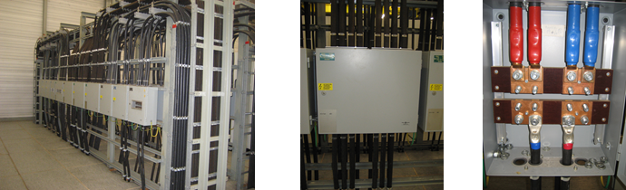
Power Part
Two units are accommodate in one enclosure.
The transformer primary is delta wired and the secondary is a star connection with star point brought out. The secondary feeds a 3 phases thyristor bridge assembly.
The secondary circuits are protected against negative voltage with two Free Wheeling diodes connected across the output.The DC output is connected to a polarity reversal switch, allowing the output voltage to be connected normally, inverted or disconnected from the load.
| Power In | 3 ~ 400V/150A |
| Power Out | 500A/150V |
| Cooling type | Fans |
| Converter Weight | Power module 1000 kg (Supply crate included) |
| Converter Size | width: 1500mm |
| depth: 1500mm | |
| height: 2300mm |
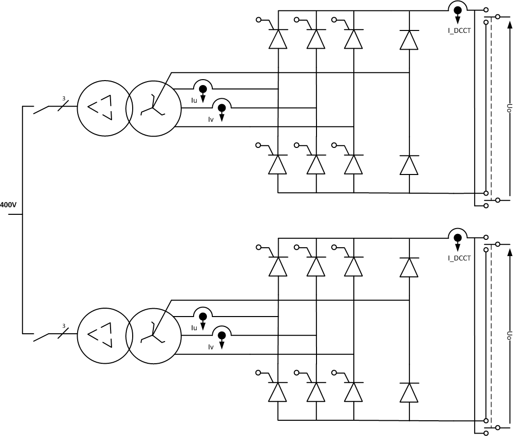
Power Part simplified Architecture / Topology .pdf
Control & Regulation Part
Control: The new VME crate is in operation since 2006 and replaced the old junction crate. It's the heart of the control system, there is one crate installed per building.
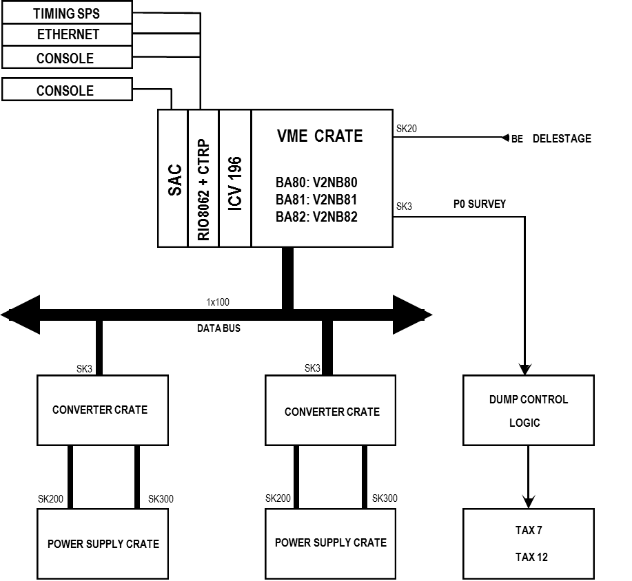
Control system simplified schematic
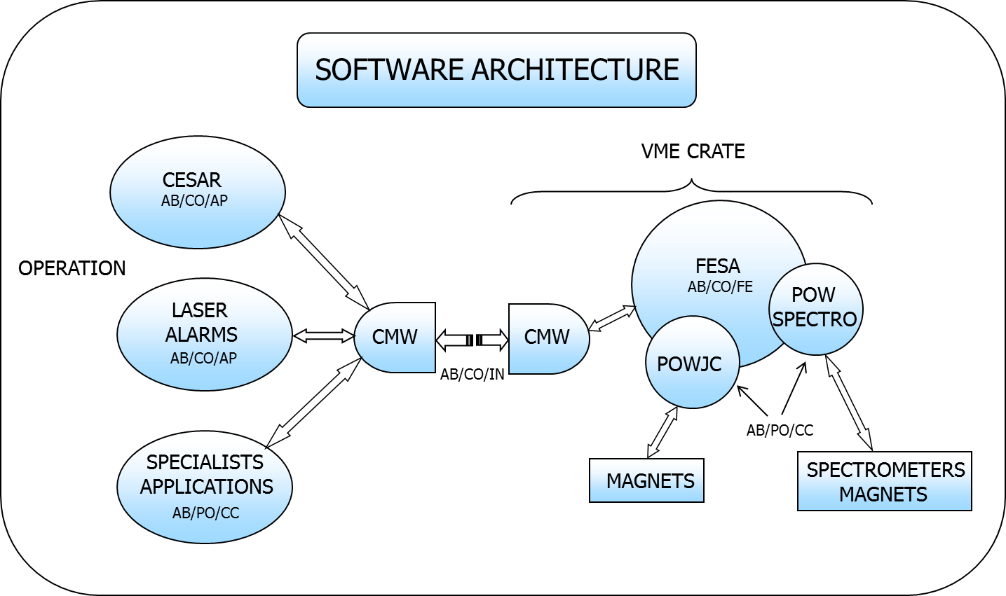
Software architecture simplified schematic
Software used to control North power converters:
Regulation: Regulation of the output current and voltage is achieved with two loops, one for the voltage and one for the current. The voltage loop ensures fast correction of the output for perturbations on the incoming mains supply. The current loop ensures stabilisation for low frequency perturbations and has a variable integration time constant selection possibility. The voltage loop feedback is from a resistor potential divider network connected across the final output. The current loop is driven by a remote controlled precision reference source (DAC). A precision current transducer (DCCT) measures the output current and produces a voltage developed across high precision and stability resistors (burden). A precision comparator amplifier with very high gain, compares the DAC and DCCT signals and produces a voltage to drive the voltage loop of the regulator. The regulator circuit develops a control voltage (-5 to +7V) from the above two loops, to control the firing of the thyristor bridges. The firing of the thyristors in the bridge, which is synchronised with the 50 Hz incoming supply, occurs at a 300 Hz frequency. During operation such as Polarity Switch change and under fault circumstances, the Blocking signal acts directly on the Thyristor trigger drivers to inhibit the output firing circuits.
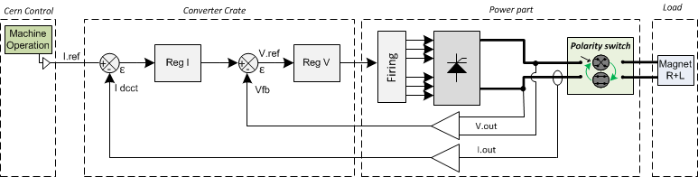
Regulation Control simplified schematic .jpg
Magnet Protection
Each magnet connected to a North Area Power Converter can have a number of bits of feedback data for monitoring its status.
These can be as follows depending on the magnet involved:
- Water Pressure: This is a pressure sensor installed at the input of the cooling loop, integrated in the magnet. This alarm can also be triggered by a water flow sensor installed on some Eletta water cooled cables, which is wired in series with the magnet alarm. There is no separate alarm given.
- Water Temperature: This is a temperature sensor located at the exhaust side of the cooling loop.
- Coil Temperature: This is a series of temperature thermostats selected to protect the appropriate magnet against excessive coil temperature.
- Rheostat: This is no longer used, except to indicate a fault on the Eletta water cooled cables on GOLIATH magnet.
- Red Button: This is an Emergency Off switch located on the magnet to allow shut down of the associated Power Converter(s) in the event that someone working in the vicinity detects a fault. The Red Button alarm can also come, for selected Power Converters, from a contact on the Access System which is in series with the Red Button of the magnet.
- Terminal Box: This is a door interlock switch located on the second terminal box, installed between the Power Converter and the magnet. This interlock can be bypassed on the Power Control Crate by inserting a jumper on the front panel.(Safety procedures are affected by this action).
- Earth Fault: Monitor Earth current of the total circuit: converter + load (magnet and its DC cables), and take the right action if threshold reached. All four positive output points before the Polarity Switch are strapped together and connected to the Earth Leakage Protection sensor relay. Activation of the Earth Leakage sensor relay for either Power Converter will be indicated in the status data
Activation of any of the above signals automatically causes the Stop signal to be generated, causing the Reference Current value to go to zero, followed 30 seconds later with the switch off of the MCB, if the Polarity switch is not in the Stop position. This is initiated by the MCB Release signal.
Magnet connection
In North area, there are two ways to connect a power converter to a magnet:
- Terminal Box (TB): Two terminal boxes are installed between the power converter and the magnet, one in the auxiliary building and the other one in the experimental area.
- Line selector matrix: Some Power Converters in building BA81 are connected to a Line Selector Matrix for routing the output to different locations in the area. The matrix can only be configured manually and the contacts are rated for a maximum of <1000 Amps, restricting which type of Power Converter can be routed in this fashion.The purpose of this is to purely provide some flexibility when configuring the different experimental beams.
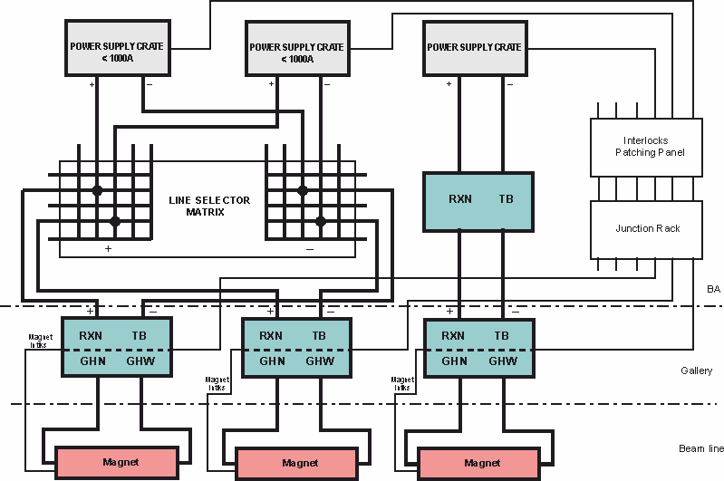
Magnet connection simplified schematic
Terminal boxes
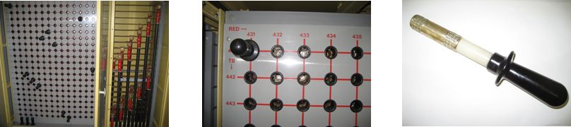
Line selector mattrix
Magnet Types
R11 power converters supplies the following loads:
- QUAD Magnets QNL, QTS, QNR, QWL, QFS
- TRIM Magnets MDX, MDS
- Magnetic Collimator XCM
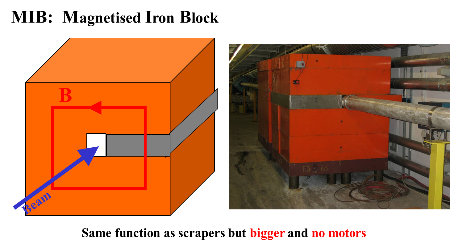
- Magnetised Iron Block MIB
Machine Installation
Number of R11 power converters installed in North area:
- 889 (BA80): 41
- 890 (BA81): 58
- 891 (BA82): 08
Production Contract & Contract History
- Manufacturer: BBC
- Production year: 1976