|
POPSB - MPS / Main Power Supply |

|
 |
|
 |
CERN
|
SY
|
SY-EPC
|
HOME
|
CERN
|
SY
|
SY-EPC
|
HOME

|
|
| |||||||||||||||||||||||||
| RPOPB | GENERAL ELECTRIC |
| Power In | 3 ~ 18KV/1950V 2.5MVA |
| Power Out | 5.6KA/3050V |
| Converter Type | Capacitive Storage |
| Control type | General electric Control + FGC3 |
 Operation Responsibles
| 1st Intervention |  Piquet SY-EPC Injector(160391) Piquet SY-EPC Injector(160391)
|
| Responsibles: | Fulvio BOATTINI |
| Arnaud BESSONNAT | |
| Aramis SCHWANKA TREVISAN |
Power Converter Architecture
POPSB supplies the PSB magnets without drawing all the power from the network. A storage capacitor bank connected on the DC side provide power decoupling from the network. The storage capacitance is around 0.3F (@5kV Udc nominal)
This exchange of energy between the capacitor banks and the load is controlled by a DC/DC converter. The system is connected to the electrical network by a AC/DC converter (Active Front End). This converter charges the capacitor banks and supplies the losses of the load and of the converters.
Dipole and quadrupole magnets of the PSB accelerator are grouped in two independent series (Magnet string 1&4 and Magnet string 2&3 in Figure 2) each one powered by one POPSB.MPS power converter.
In total there are three POPSB.MPS power converters:
The three POPSB.MPS power converters are identical.
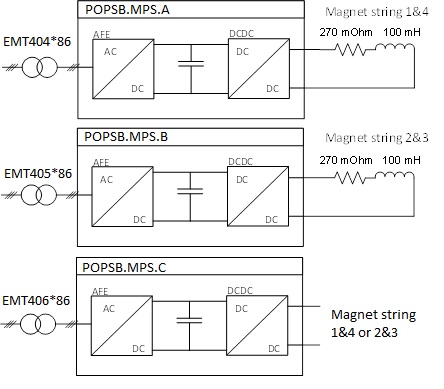
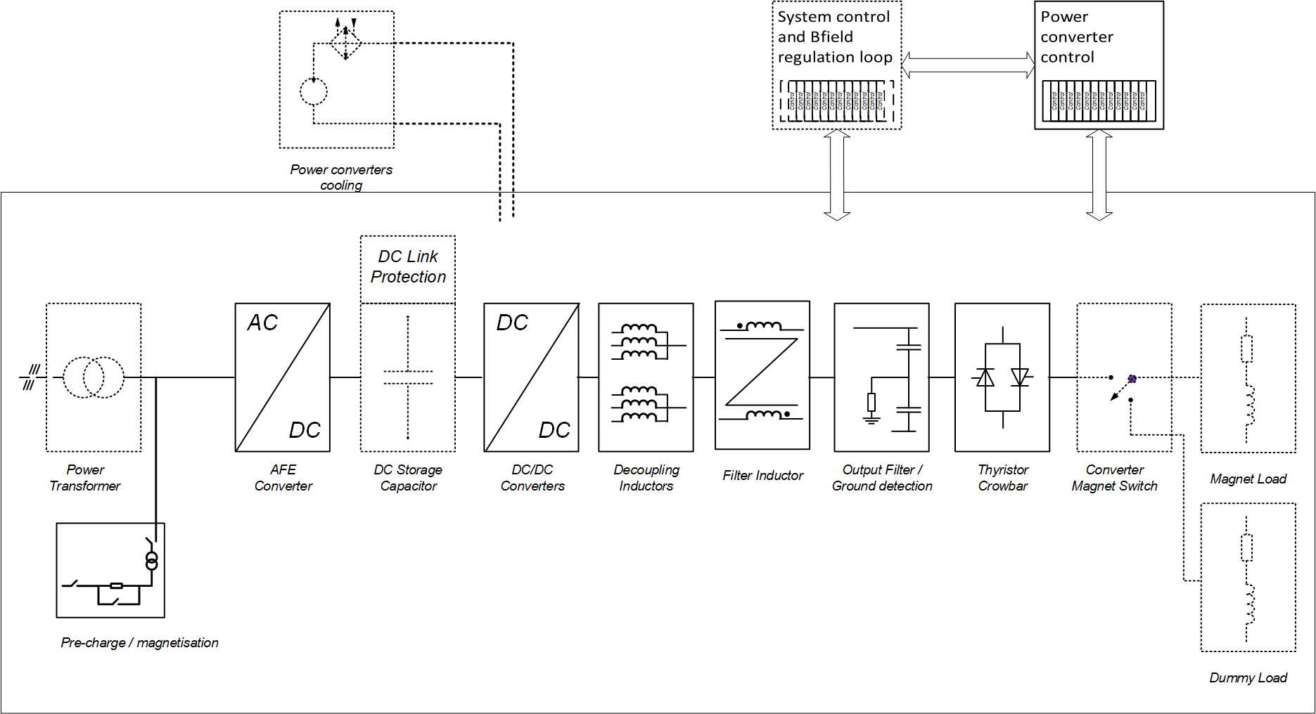
POPSB.MPS converter architecture
Power Part
| Power In | 3 ~ 18KV/1950V 2.5MVA |
| Power Out | 6KA peak,3KA rms/3KV |
| Cooling type | Demineralized water |
The POPSB.MPS power converter is composed of an AC/DC (AFE) units which supply power to a DC/DC power converter. The capacitor banks are used to exchange the energy with the PSB magnets during converter pulsing operation.
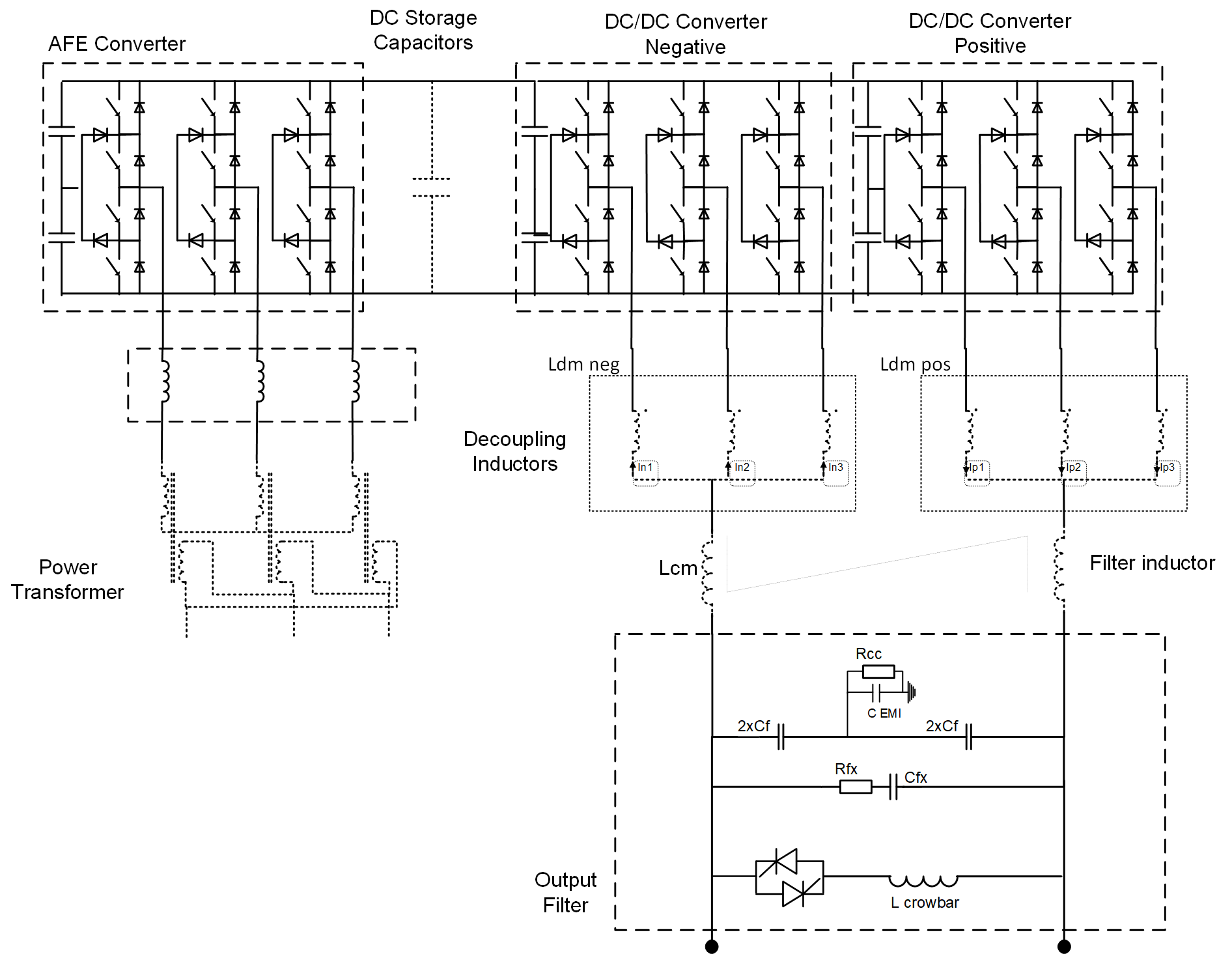
POPSB power converter schematic diagram
As the current in the magnets rises, the voltage across storage capacitors drops. The energy stored in the magnets is then given back to capacitors at the end of the cycle. In this way the AFE converter provides only the losses required by the magnets and the converter itself.

POPSB Magnet current & voltage
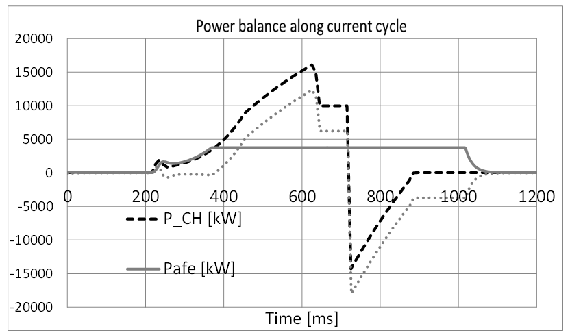
POPSB Power balance
Control & Regulation Part
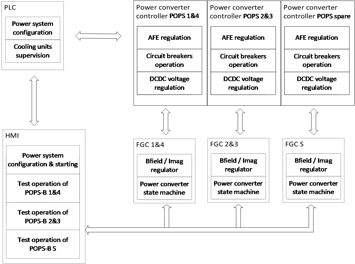
POPSB power converter schematic block diagram
POPSB control functional diagram
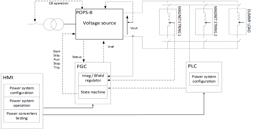
POPSB control scheme
The supervision application has been developed at CERN using the technologie WinCC-OA-UNICOS.Many views were developed for the operation and diagnostic: detail view on the AC/DC, DC/DC, capacitors banks, interlocks, etc.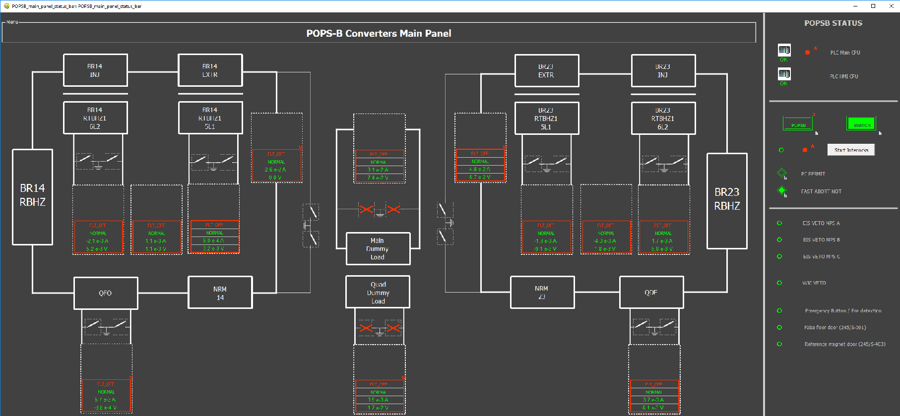
POPSB HMI view
Magnet Protection
The booster magnets are protected by a WIC (Warm Interlock Controller) system installed in the BT, BTP, BTM transfer lines.
The WIC is a Programmable Logic Controller (PLC) based system. It protects the normal conducting magnets from overheating by switching off the power converter when a fault occurs.
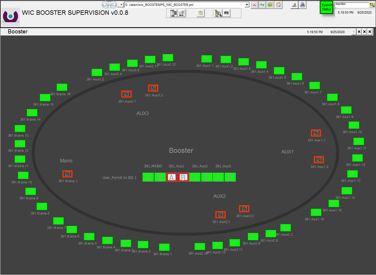
PSB WIC supervision
Magnet connection
- Main Magnets / Power Converters connections: The PSB main magnets can be supplied by POPSB or BR_MPS system. The power switch RSOPS.271.RMPS.1 located in the 271 building allows to select the desired power conveter.
- Magnets are split into 2 equivalent series and 2 separated power converters are used to power each half string of magnets:
- Rings 1&4 + QFO
- Rings 2&3 + QDE
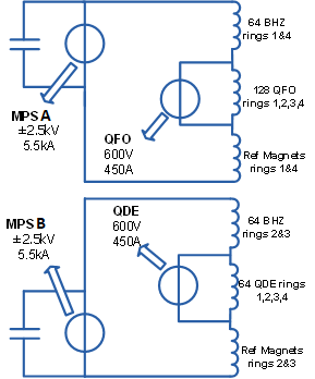
POPSB Circuit connection
Magnet Types
- Dipole magnets: The BHZ MAIN bending magnet as shown in the picture below features four vertically stacked apertures.
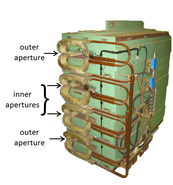
Dipole magnet.
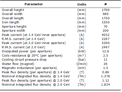
BHZ Main magnet characteristics.
- Quadrupole magnets: As per the BHZ magnets the QFO and QDE quadrupole magnets feature four vertically stacked apertures.
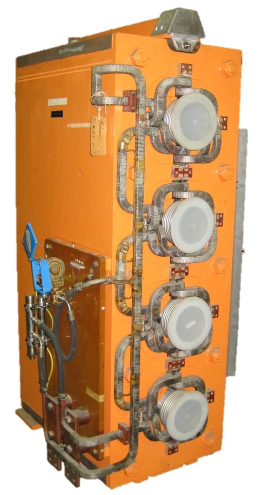
QDE Quadrupole magnet.
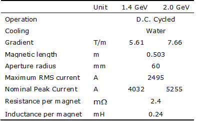
QFO magnet parameters.
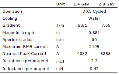
QDE magnet parameters.
- Reference: Proton Synchrotron Booster (PSB) Main Ring Bending and Quadrupole Magnets for 2.0 GeV Operation
Machine Installation
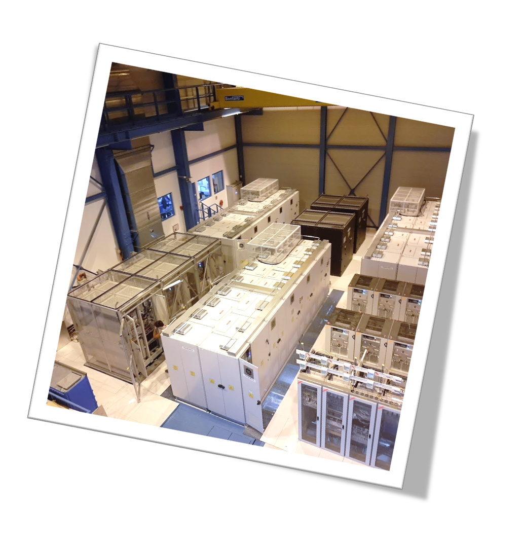
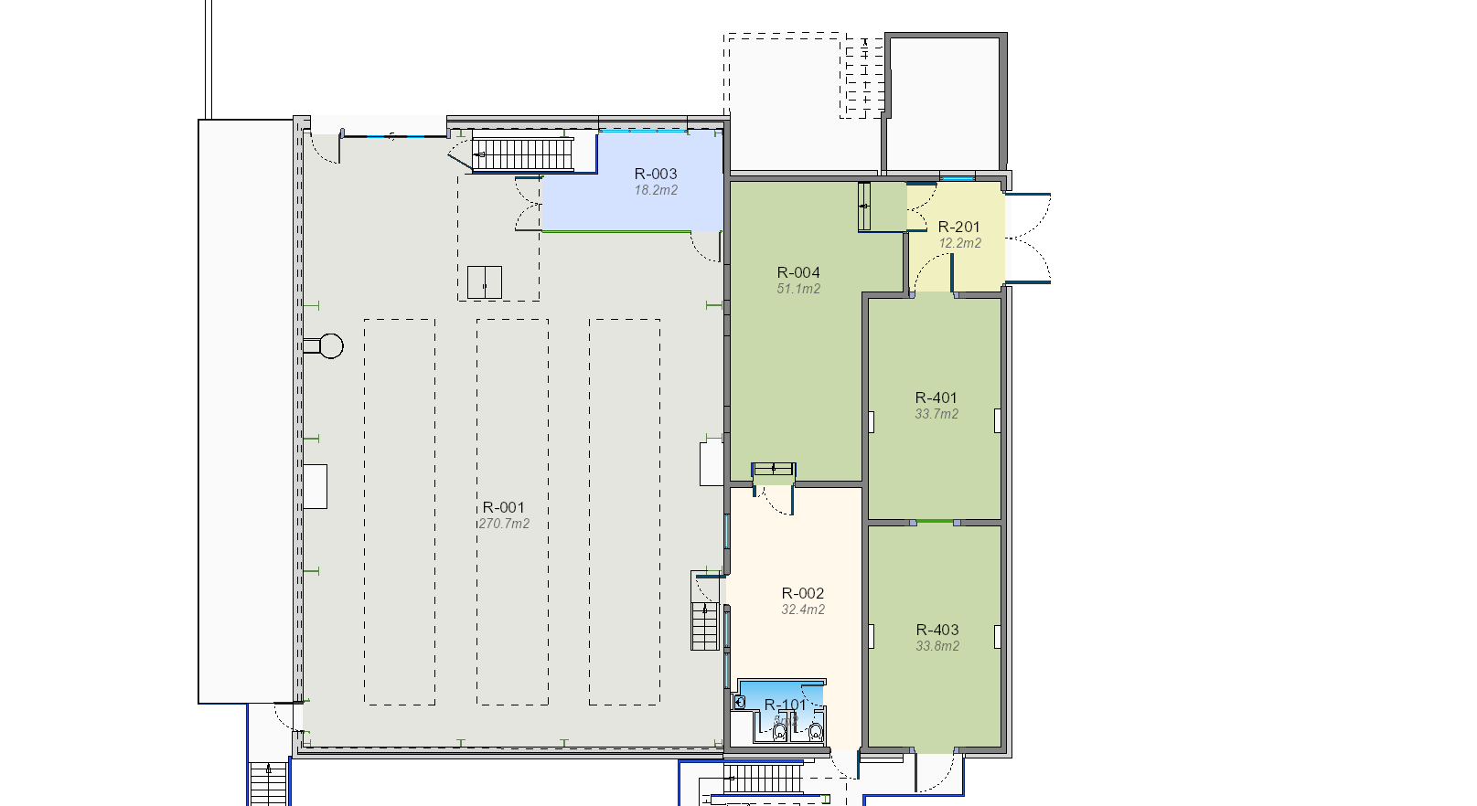
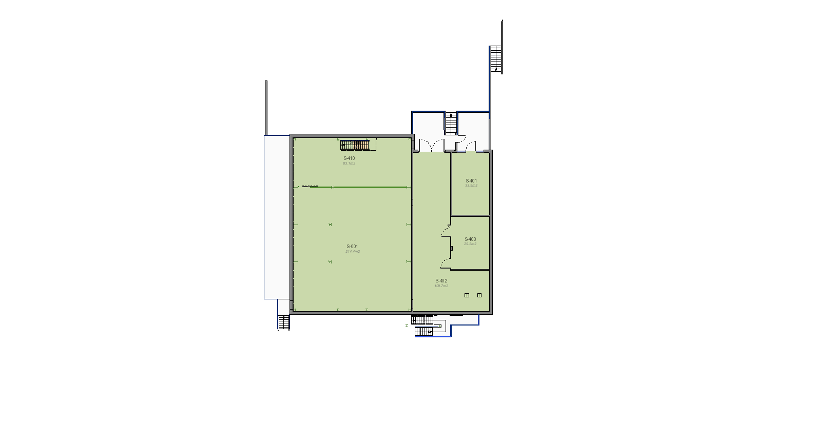
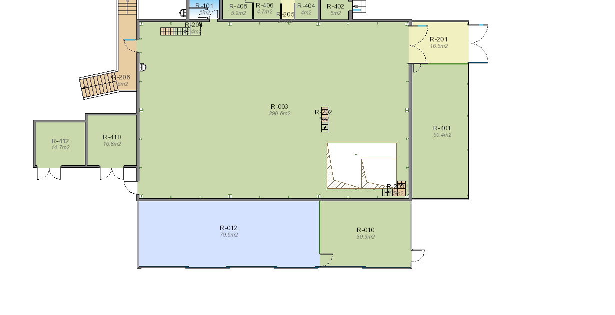
The POPSB equipements are installed inside the building 245:
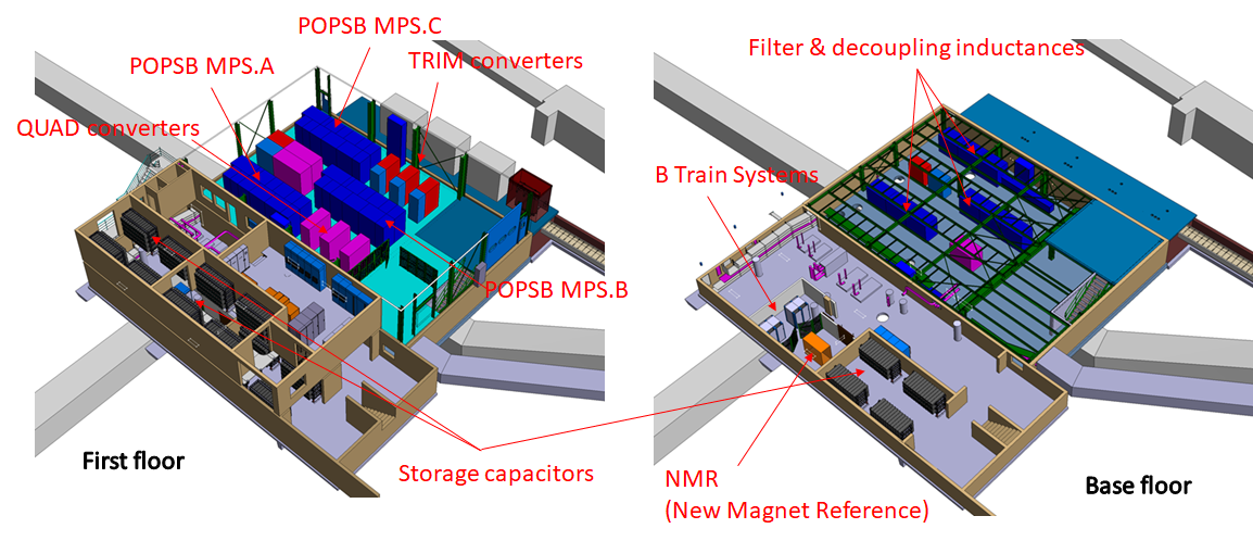
POPSB 245 Layout
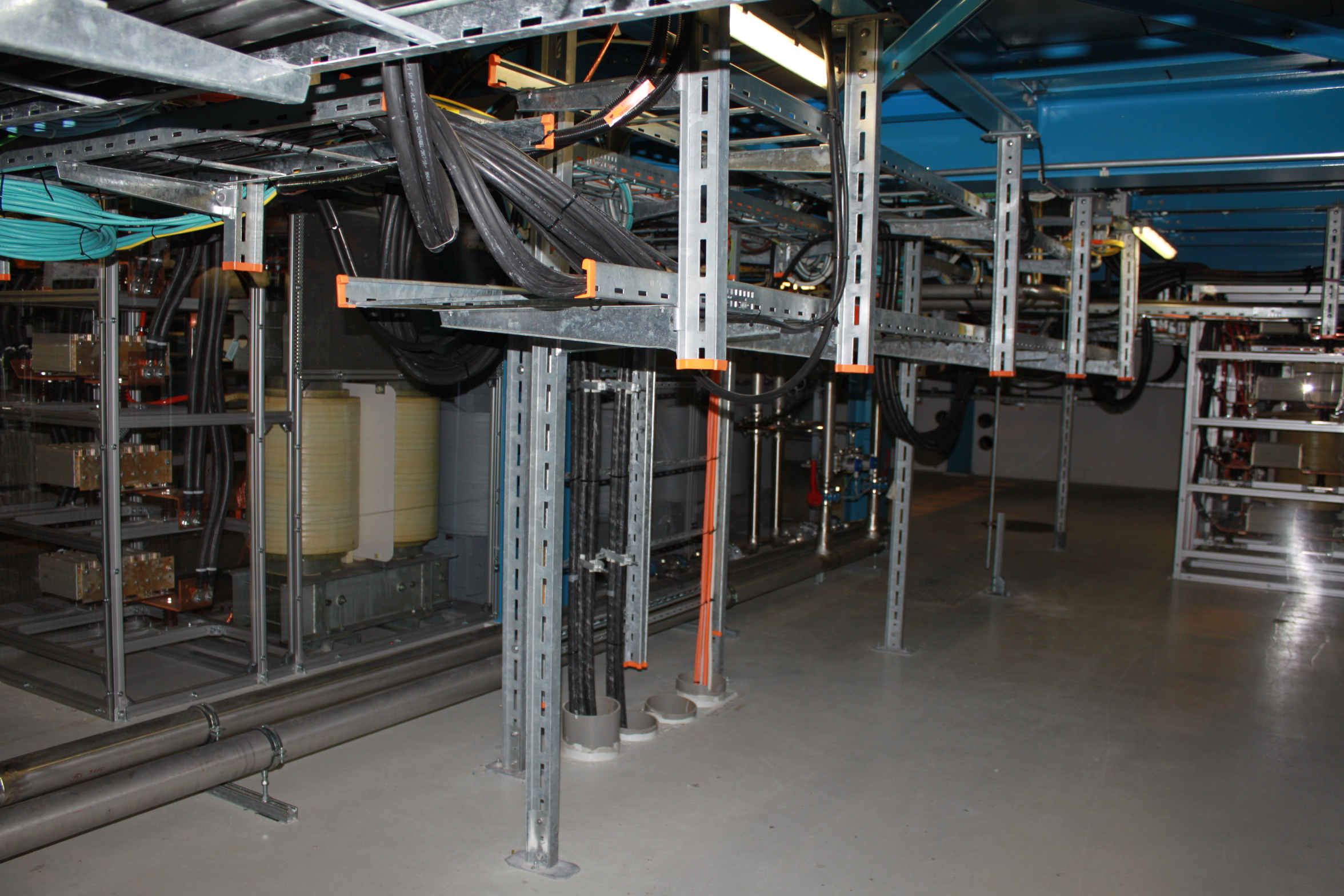
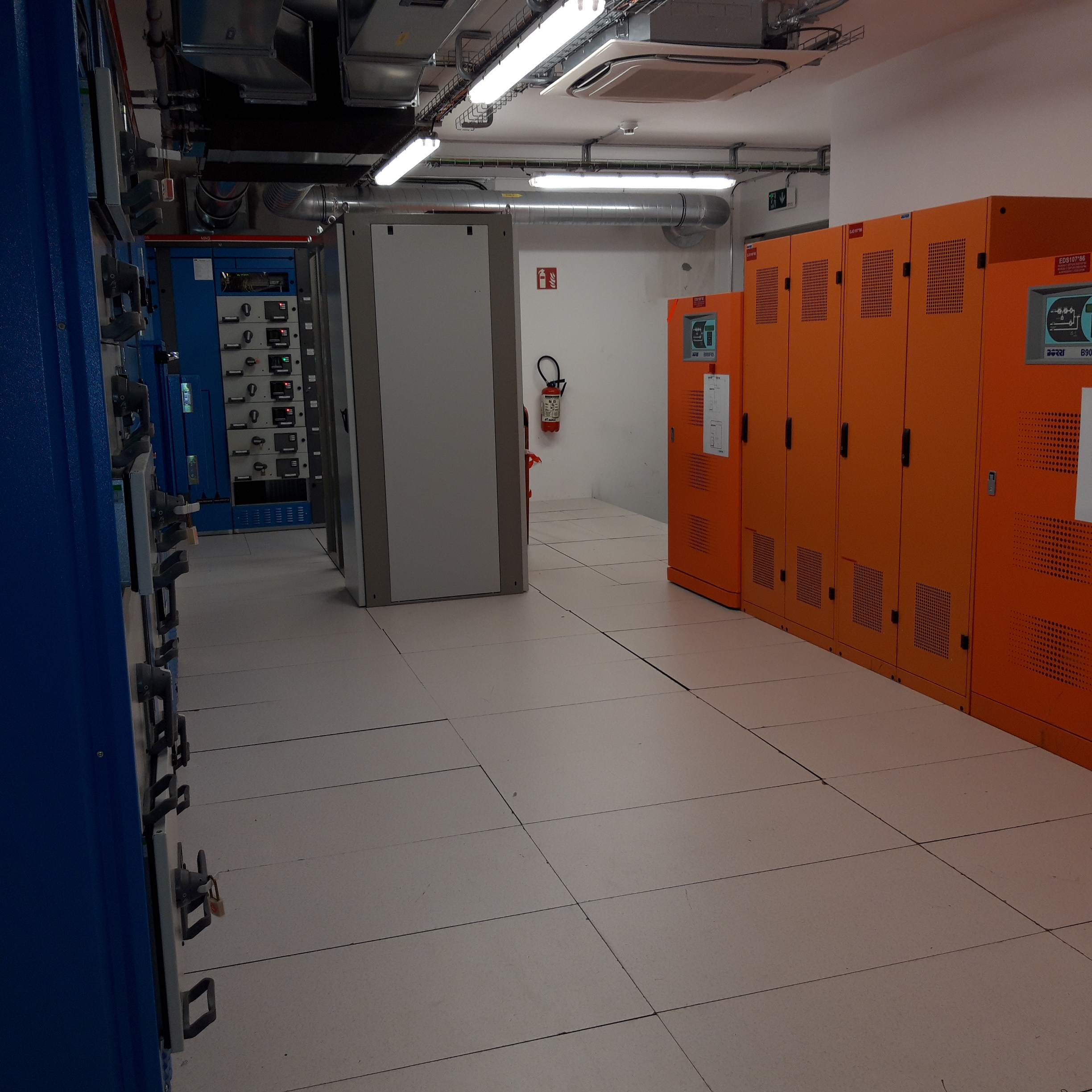
- 245 R-001: Power Converters Room
- 245 S-001: Decoupling inductances under false floor
- 245 R-002: POPSB Control Room
- 245 R-004: Electrical room
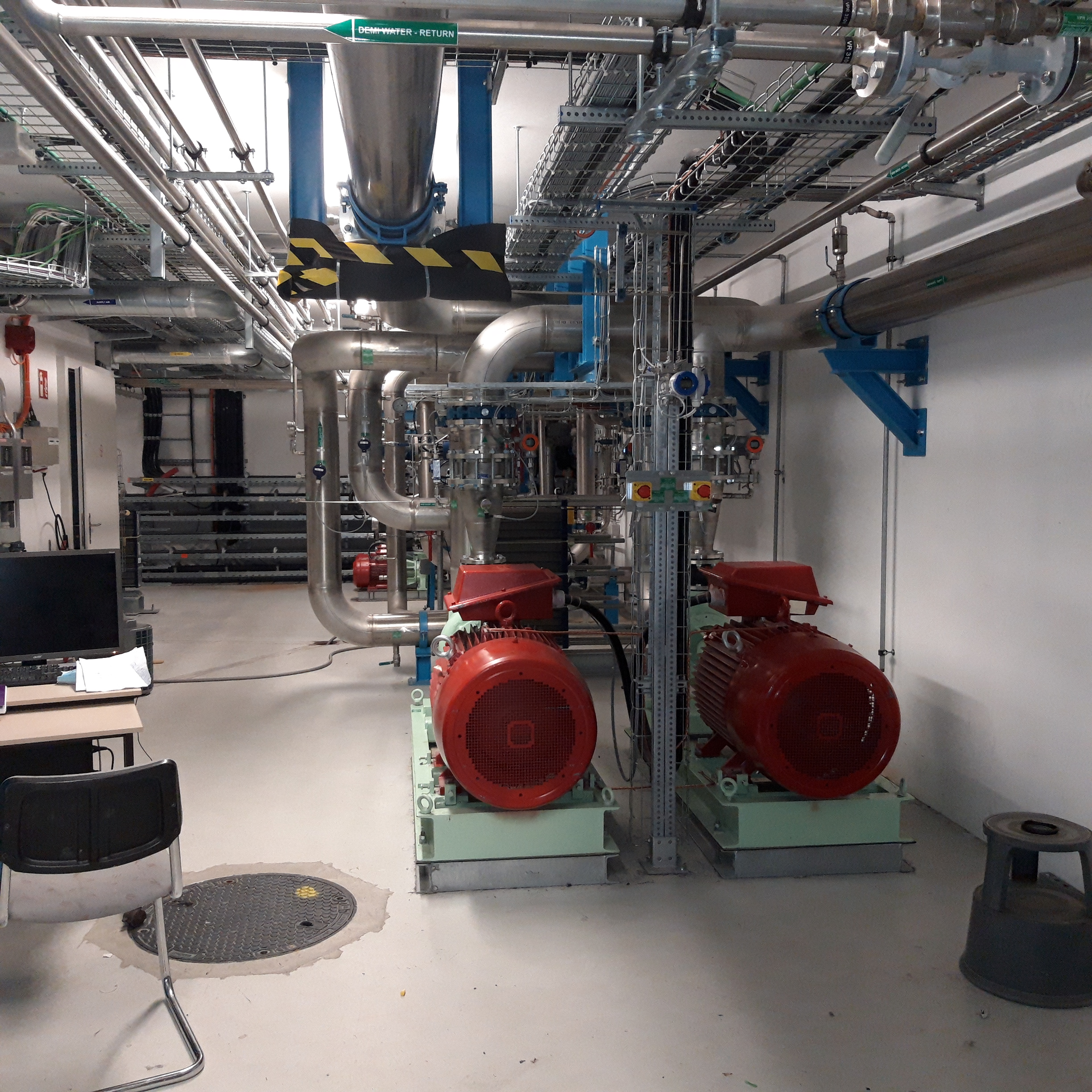
- 245 S-402: Cooling & Ventilation Room
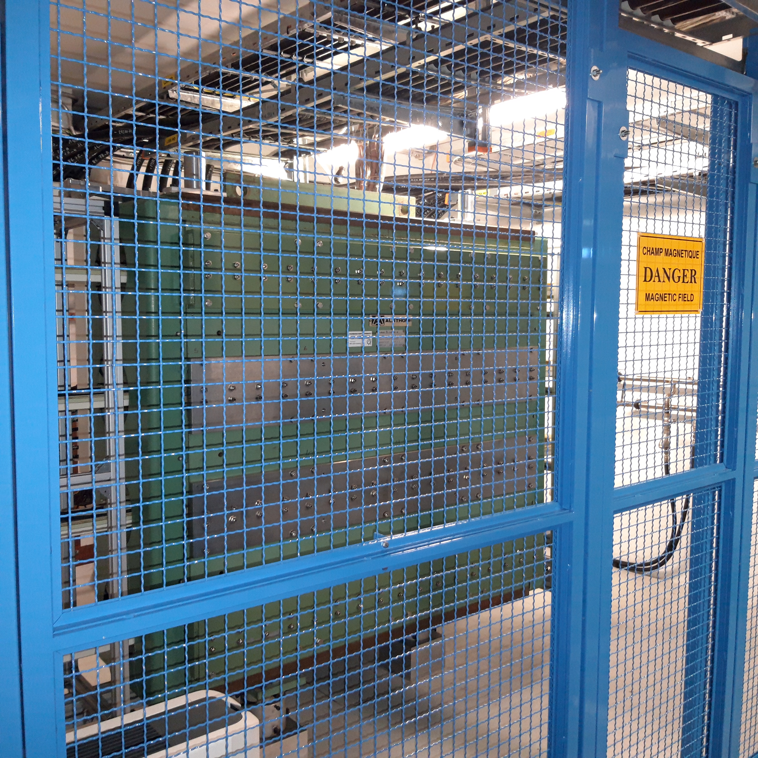
- 245 S-403: Reference Magnet Room
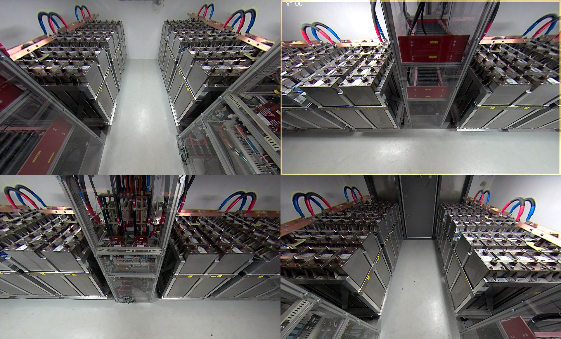
- 245 S-401: Capacitor room MPS.B
- 245 R-401: Capacitor room MPS.A
- 245 R-403: Capacitor room MPS.C
- 367 R-012: Dummy Load Room
Production Contract & Contract History
- Manufacturer: GENERAL ELECTRIC
- Production year: 2018
- First cycle in PSB Magnets: December 2018
- First beam in PSB with POPSB: 2021