|
POPS / Power for PS |

|
 |
|
 |
CERN
|
SY
|
SY-EPC
|
HOME
|
CERN
|
SY
|
SY-EPC
|
HOME

|
|
| |||||||||||||||||||||||||
| POPS | CONVERTEAM |
| Power In | 3 ~ 18KV/1950V 2.5MVA |
| Power Out | 6KA/10KV |
| Converter Type | Capacitive Storage |
| Control type | Converteam Control + FGC2 |
 Operation Responsibles
| 1st Intervention |  Piquet SY-EPC Injector(160391) Piquet SY-EPC Injector(160391)
|
| Responsibles: | Fulvio BOATTINI |
| Xavier GENILLON | |
| Yves GAILLARD |
Power Converter Architecture
POPS supplies the PS magnets without drawing all the power from the network. The maximum stored energy in the magnets is 14MJ. This energy is supplied by the capacitor banks (CS).
This exchange of energy between the capacitor banks and the load is controlled by DC/DC converters. The system is connected to the electrical network by two AC/DC converters (Active Front End). These converters charges the capacitor banks and supplies the losses of the load and of the converters.
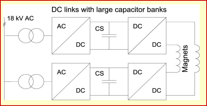
POPS Power Converter Architecture
Power Part
| Power In | 3 ~ 18KV/1950V 2.5MVA |
| Power Out | 6KA/10KV |
| Cooling type | Demineralized water |
The POPS power converter is composed of two identical AC/DC (AFE) units which supply power to six DC/DC power converters (4 floating and 2 chargers). The DC/DC converters are designated as Floatings if the relative capacitor bank is floating otherwise Chargers when an AFE is present. The capacitor banks are used to exchange the energy with the PS magnets during converter pulsing operation.
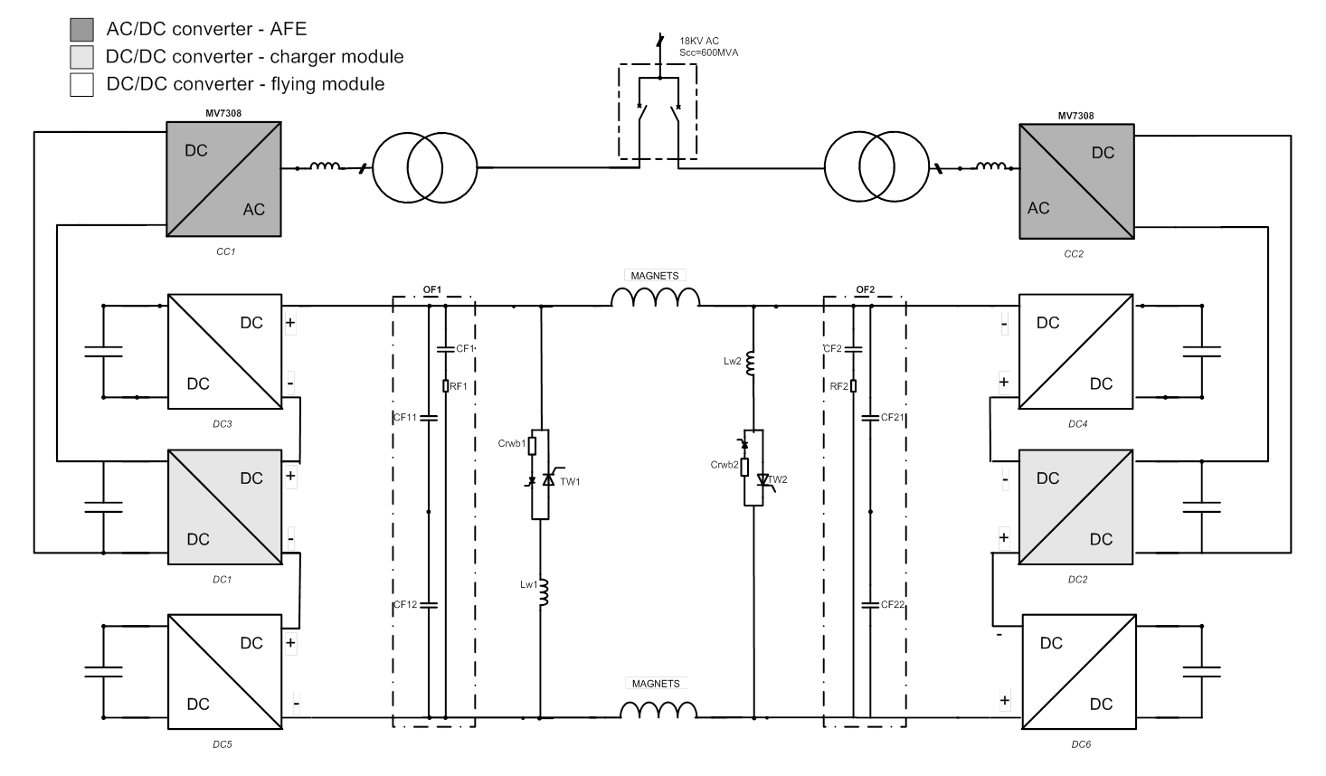
POPS Power Part simplified Architecture / Topology .pdf
As the current in the magnets rises, the voltage across storage capacitors drops. The energy stored in the magnets is then given back to capacitors at the end of the cycle. In this way the AFE converters provides only the losses required by the magnets and the converter itself.
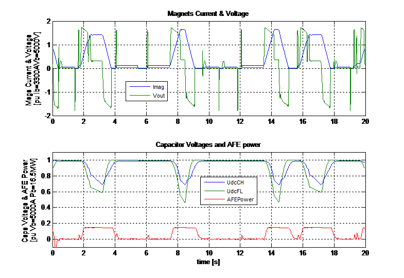
POPS capacitors discharge and AFE power during cycles
Control & Regulation Part
Control: The POPS control system is composed by two separated control hardware: the FGC (Function Generator Controller) and the MC (Main Controller). The power converter with the MC controller can be considered as a controlled voltage source, the voltage reference being produced by the master running in the FGC. The controls for the POPS is based on the FGC2 POPS controls crate containing an FGC2-80 and POPS/B-Train/Link (PBL) card. This receives the field measurement (B-Train) and supports a real-time fibre link to the POPS/Acquisition/Link (PAL) card in the POPS VME Control crate. The PAL card receives the high resolution voltage signals from the 8 POPS Acquisition Modules (PAMs) and provides the filtered voltages to the POPS CTL CPU and the FGC. The FGC is linked to the FGC gateway by a WorldFIP fieldbus segment.
The FGC runs Class 53 (POPS) software which supports the POPS converter via the PBL-PAL link.
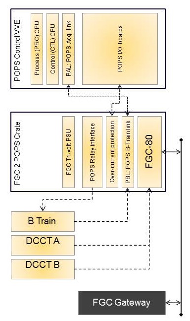
POPS Control system simplified schematic
The supervision application has been developed at CERN reusing the technologies and tools used for the LHC Accelerator and Experiments (UNICOS and JCOP frameworks, PVSS SCADA tool).About 35 different views were developed for the operation and diagnostic: detail view on the AC/DC, DC/DC, output connections, cooling, interlocks, etc.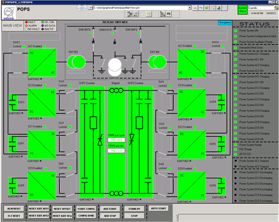
HMI View
Regulation: The main task of the POPS control system is to track very accurately the reference signal (Bref or Iref) obtained from CERN control center. The tiniest perturbation in the magnetic field (Bfield) can lead to instability and complete loss of the beam. For this reason an accuracy of 10ppm is required in the regulation of the Bfield/Imag. The control software of POPS can be divided into two main areas of pertinence. In a temporal sequence, we found first all the control loops that need to be executed to generate the output voltage reference for the power converter. Then the Voutref needs to be allocated among the DC/DC converters connected in series. All control loops in POPS are digital and they are implemented according to the RST technique.
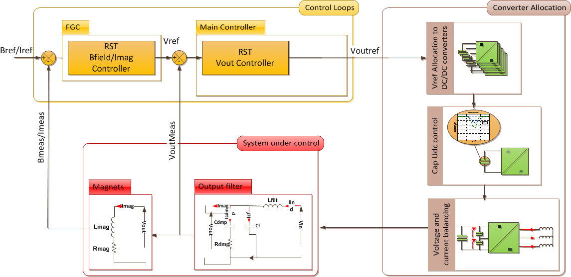
POPS Control tasks overview
Magnet Protection
The magnet interlocks are managed by the POPS External Conditions 3U Crate in the FGC Rack
There are only two magnet interlocks:
- Magnet Water Flow: This is a relay contact coming from the magnet cooling station in building 355 R-030.
- Magnet Fault: This is a relay contact coming from the PS Thermal Interlock rack located in building 355 R-009. The auxiliary 48V of the magnet is also monitoring.
Magnet Water Flow connections
Magnet Fault connections
Magnet connection
- Main Magnets / Power Converters connections: The PS main magnets can be supplied by POPS or MPS system. A power switch located in the 358 1-414 building allows to select the desired power conveter.
PS Main Magnet/Power converters connection simplified schematic
Magnet Types
MPS power converters supplies the main coils of the 101 PS main magnets. 100 of them are installed in the PS machine and the 101eme is a reference magnet located in the building 355 R-14.
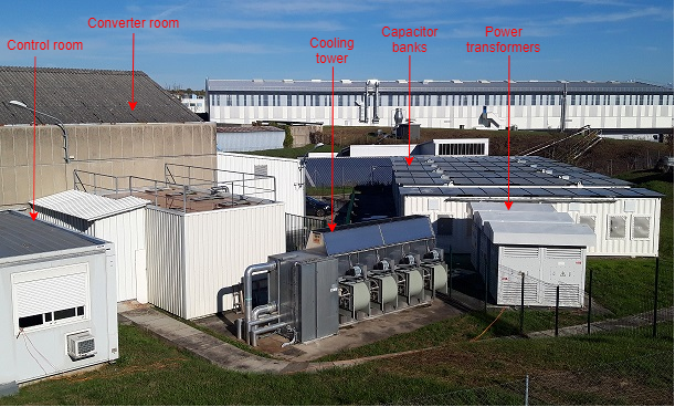
Machine Installation
The POPS equipements are installed inside and around the building 367:
- 367 R-003: Power Converters Room
- 367 R-410: DXP Output Filters Room
- 367 1-401: Main Controler Room
- 6103: POPS Control Room
- 367 R-012: Dummy Load Room
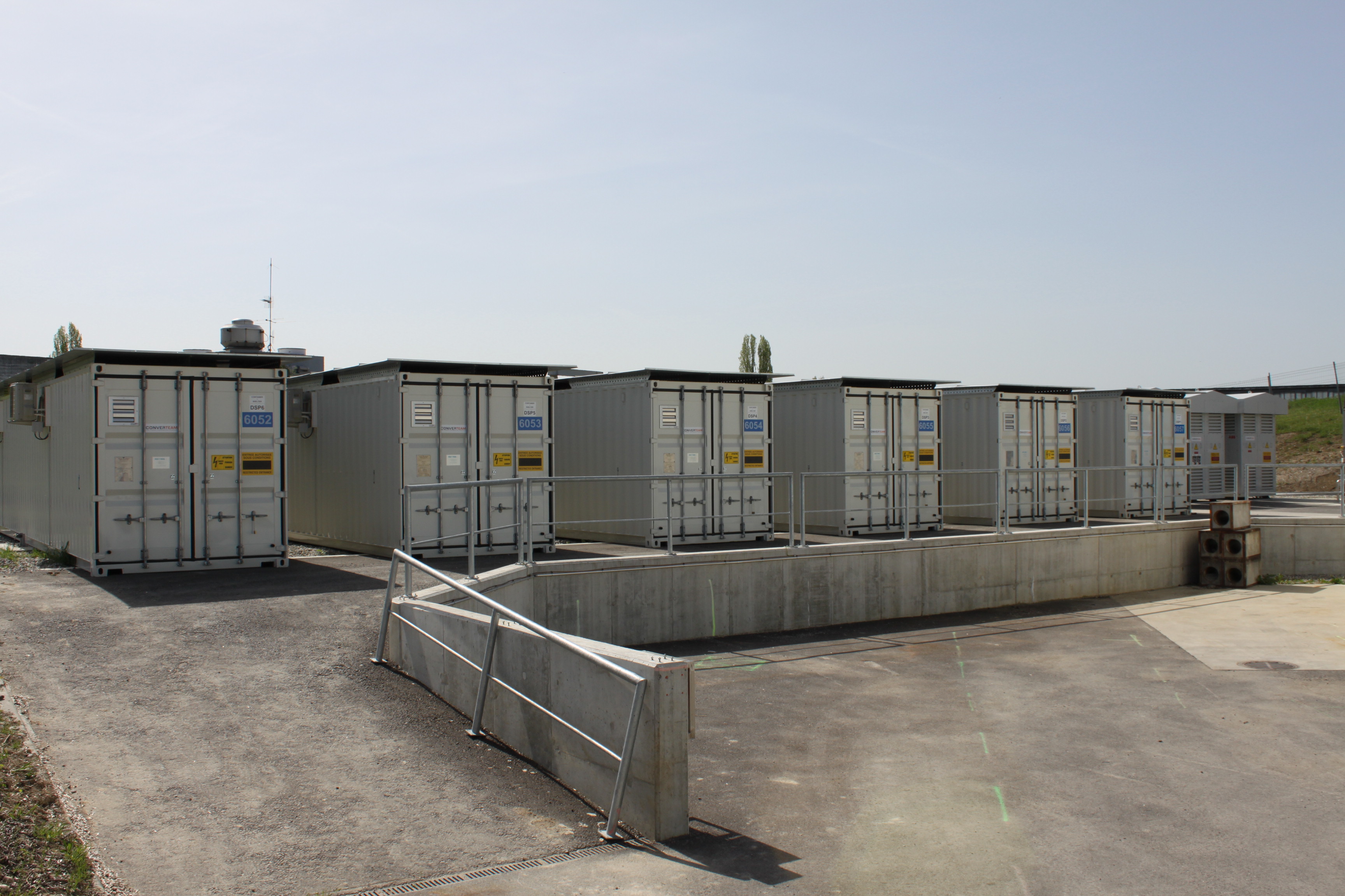
- 6057: Container DSP1
- 6056: Container DSP2
- 6055: Container DSP3
- 6054: Container DSP4
- 6053: Container DSP5
- 6052: Container DSP6
Production Contract & Contract History
- Manufacturer: CONVERTEAM
- Production year: 2010
- First beam in PS with POPS: 11/02/2011 11.11am