|
MPS / SIEMENS |

|
 |
|
 |
CERN
|
SY
|
SY-EPC
|
HOME
|
CERN
|
SY
|
SY-EPC
|
HOME

|
|
| |||||||||||||||||||||||||
| MPS | SIEMENS | |
| Power In | Motor 3 ~ 18KV/6KV 7MVA | Generator 3 ~ 18KV/190V 462KVA |
| Power Out | 5500A/9000V | |
| Converter Type | Thyristors 12P | |
| Control type | PLC Siemens S7 |
 Operation Responsibles
| 1st Intervention |  Piquet SY-EPC Injector(160391) Piquet SY-EPC Injector(160391)
|
| Responsibles: |
|
|
|
Power Converter Architecture
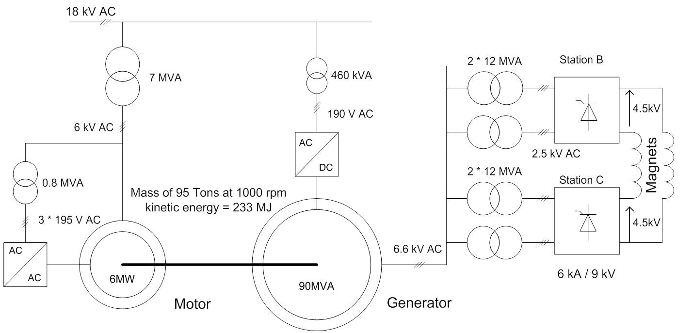
To avoid drawing the power pulses directly from the internal 18 kV CERN AC-mains (Pcc= 600 MVA), an M-G set is inserted between the mains and the load.
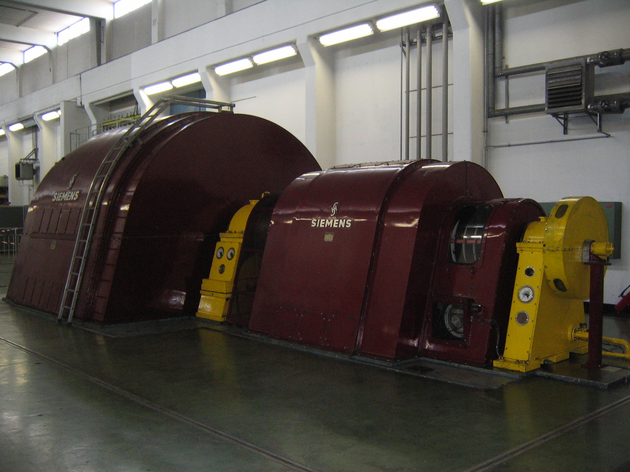
The motor is connected to the 18kV network by a 7 MVA transformer and drag the 80 ton rotor of the generator at 1000 rpm.
The generator drives a 6.6 kV network feeding the four 12 MVA transformers of the rectifiers, which power the magnets by delivering a voltage of 9 kV and a DC current up to 5.5 kA peak (3.2 kA rms, limited by the magnets).
The M-G set, which acts as a fly-wheel with a stored kinetic energy of 233 MJ at nominal rotating speed, evens out the pulsed power to be delivered by the mains. The motor power is controlled via frequency converters exciting the rotor windings and is kept roughly constant at 6 MW.
During continuous operation the rotating speed of the M-G set varies, i.e. the speed is brought to over-synchronism (up to +2 % of nominal speed) between PS acceleration cycles and falls (to -2 % minimum) during a cycle.
MPS Power Converter Architecture
Power Part
| Power In | Motor 3 ~ 18KV/6KV 7MVA | Generator 3 ~ 18KV/190V 462KVA |
| Power Out | 5500A/9000V | |
| Cooling type | Demineralized water |
Power Part simplified Architecture / Topology .pdf
Control & Regulation Part
Control: The controls for the PS MPS is based on the FGC2 2-bridge thyristor controls crate from the LHC. A variant of the FGC2 (-80) is used in combination with a converter simulator card (SIM_PCONV) which also has an interface to receive the B-train signal. An analogue voltage loop is implemented on a card in the crate and it receives the Vref signal from the DAC in the FGC. One ADC + filter in the FGC will be used to measure the converter voltage Vmeas at 1kHz. The other ADC filter will be used to acquire either IdcctA or IdcctB from external 22-bit ADCs linked to the FGC by optical fibres. The FGC is linked to the FGC gateway by a WorldFIP fieldbus segment. A new class of FGC2 software (Class 52 PC_MPC) has been written, based on the existing Class 51 PC_LHC. The new class extend the functionality with the addition of PPM support and regulation on measured field.
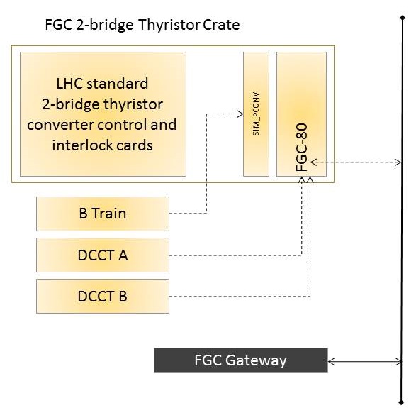
MPS FGC2 Control system simplified schematic
The MPS state is controlled by a PLC. This is programmed with sequences (graph-start and graph-stop) that start and stop the group (M-G set + thyristor converter).The HMI (Human Machine Interface) supervision of the motor-generator set, converter groups, water cooling, transformers, passive filter, etc. is done by a customized version of the standard WinCC software.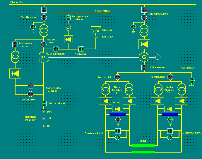
HMI view
Regulation: The reference and feedback signals of the regulation loop are related to the isocenters magnetic field density B. The magnetic field density B is the very fundamental physical magnitude on the bending magnets because it mainly defines the trajectory and stability of the particle beam. So, the servosystem managing the power converter is devoted to control this variable. Owing to technological problems, a fast and accurate enough magnetic field transducer is not available, yet. Hence, several approaches were developed in the past to obtain a useful feedback signal as close as possible to B in a single loop topology. Firstly the filtered output voltage UF was used, then the output current and finally the d|B|/dt, which is in use at present.
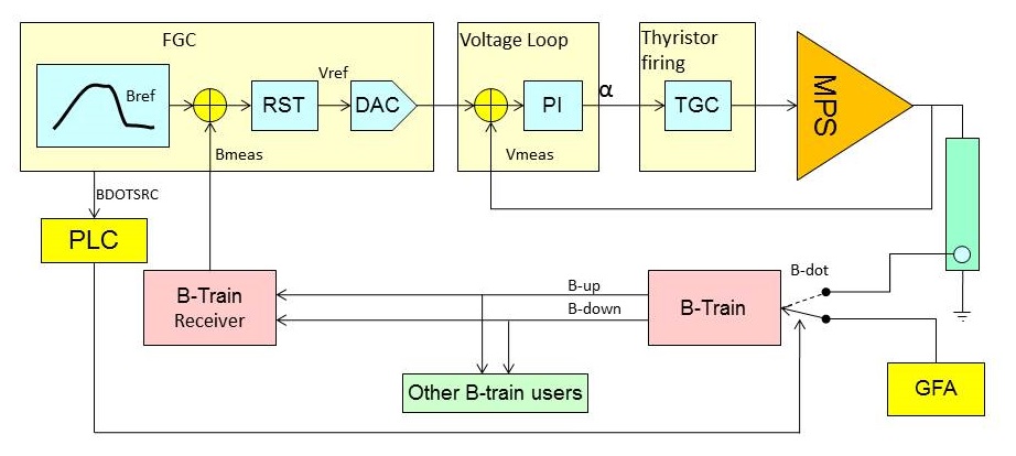
Regulation system simplified schematic
Magnet Protection
The magnet interlocks are managed by the PLC in LD1 Rack
There are only two magnet interlocks:
- Magnet Water Flow: This is a relay contact coming from the magnet cooling station in building 355 R-030.
- Magnet Fault: This is a relay contact coming from the PS Thermal Interlock rack located in building 355 R-009. The LD1/PLC also monitors the auxiliary 48V of the magnet.
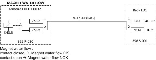
Magnet Water Flow PLC connection
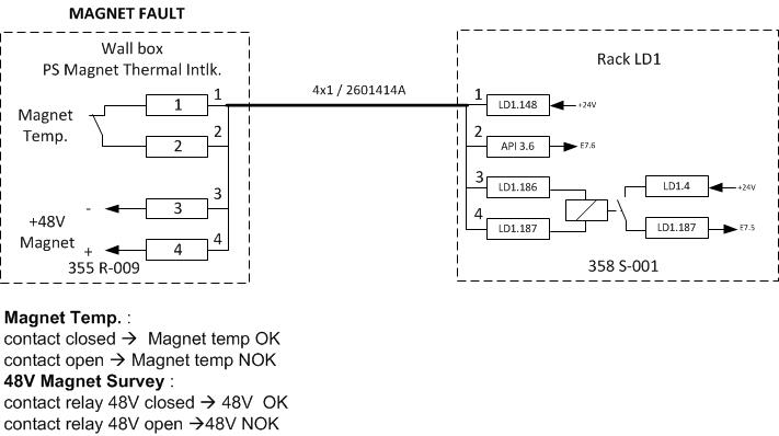
Magnet Fault PLC connection
Activation of any of the above signals automatically causes the Level 2 fault, causing the magnet current to go to zero.
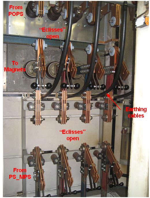
Magnet connection
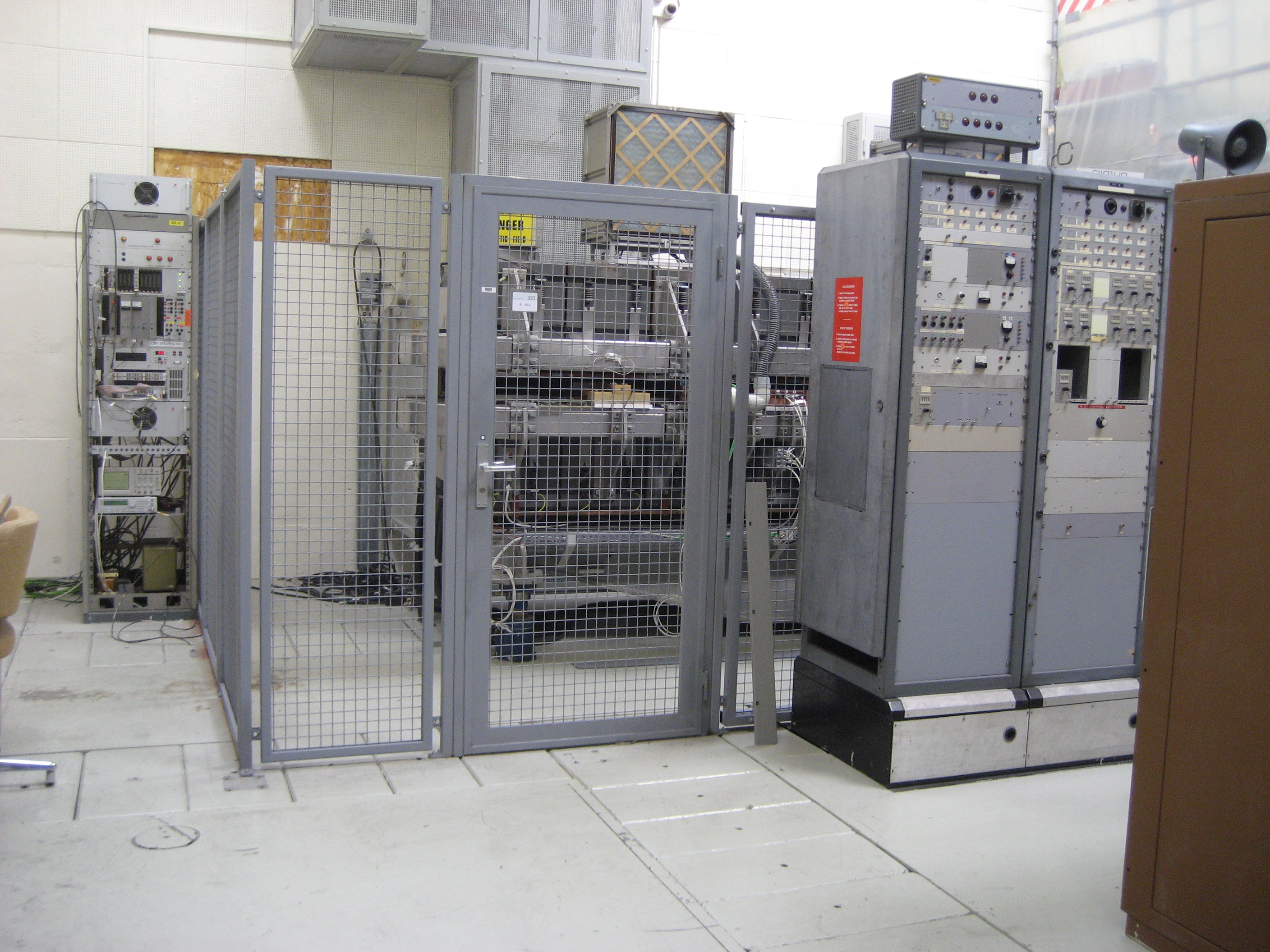
- Main Magnets / Power Converters connections: The PS main magnets can be supplied by POPS or MPS system. A power switch located in the 358 1-414 building allows to select the desired power conveter.
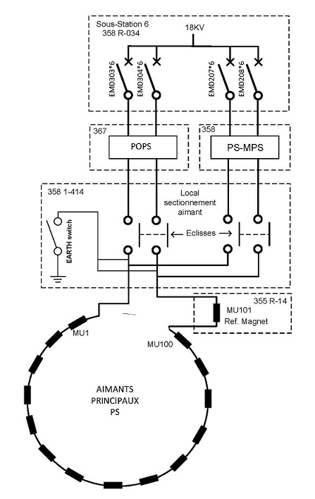
PS Main Magnet/Power converters connection simplified schematic
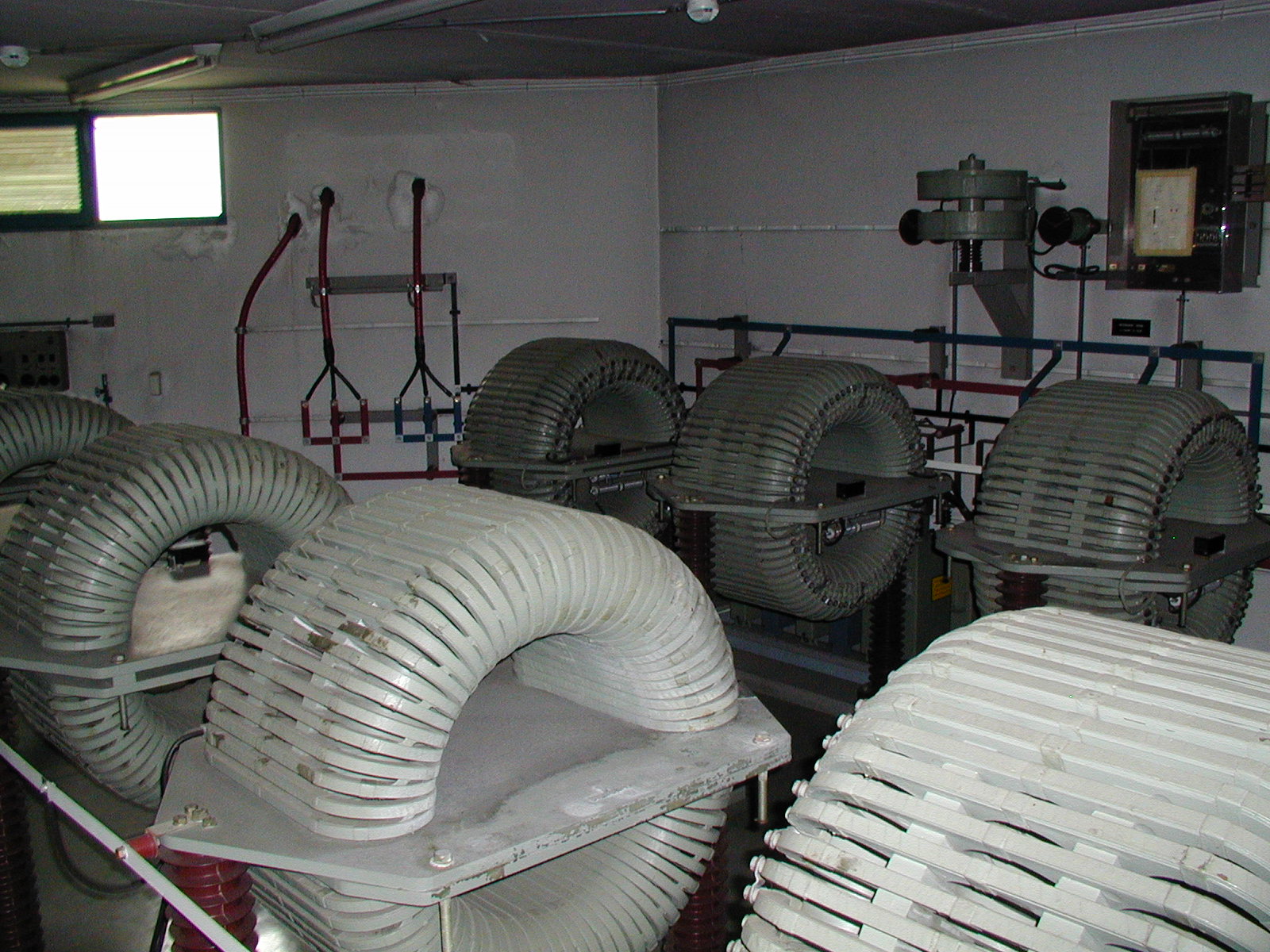
Magnet Types
MPS power converters supplies the main coils of the 101 PS main magnets. 100 of them are installed in the PS machine and the 101eme is a reference magnet located in the building 355 R-14.
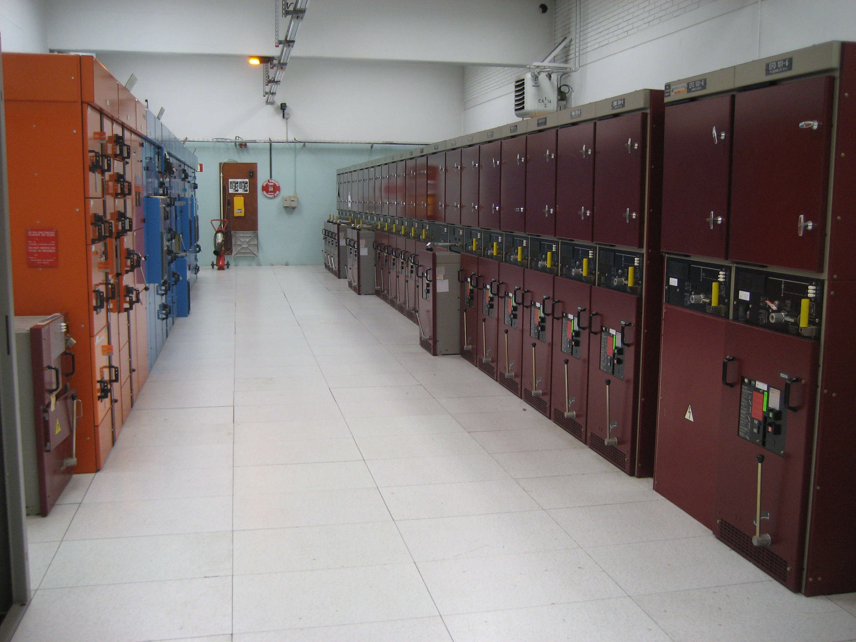
Machine Installation
The MPS equipements are installed in several buildings:
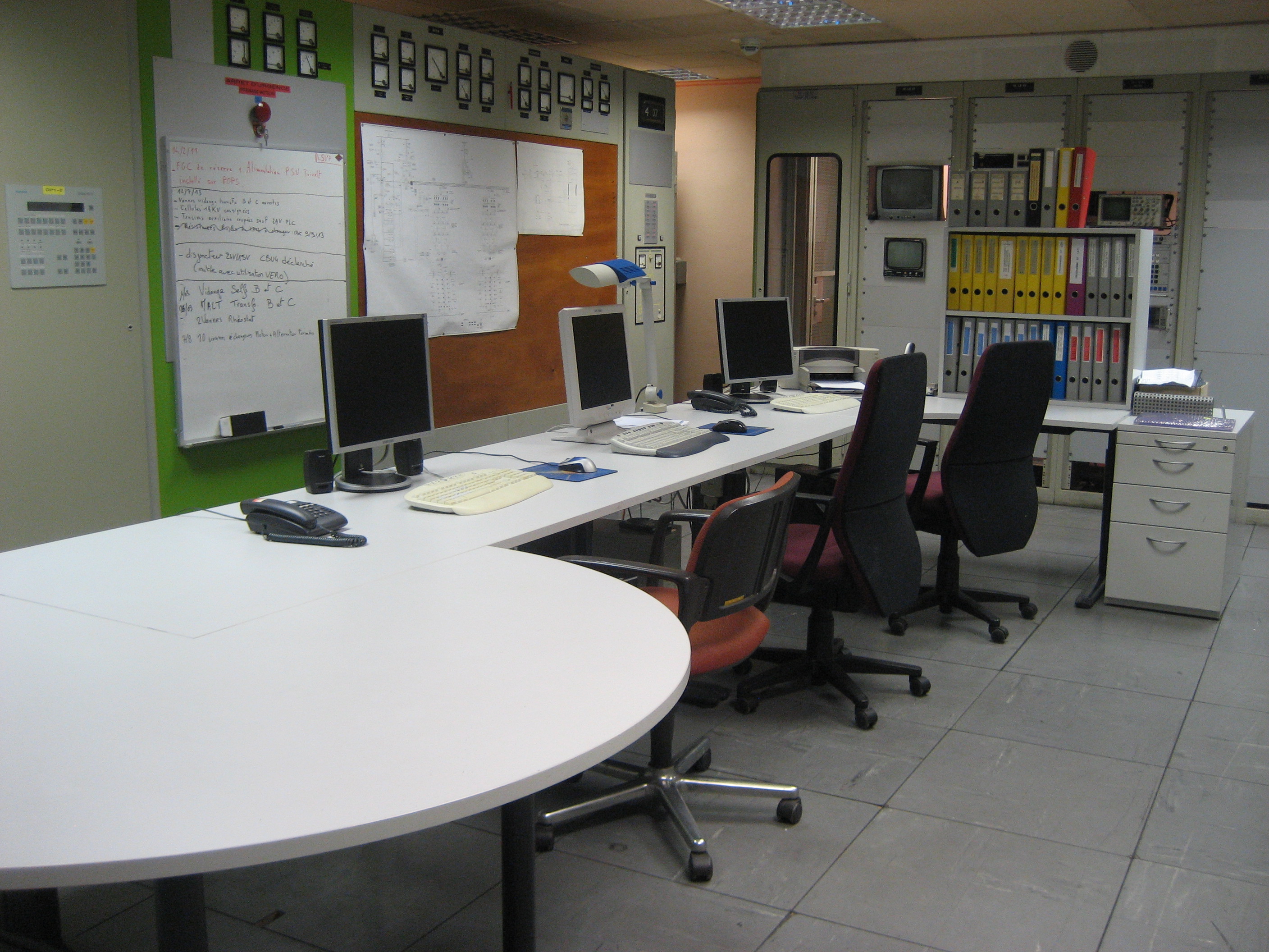
- 358 S-001: MPS Control room
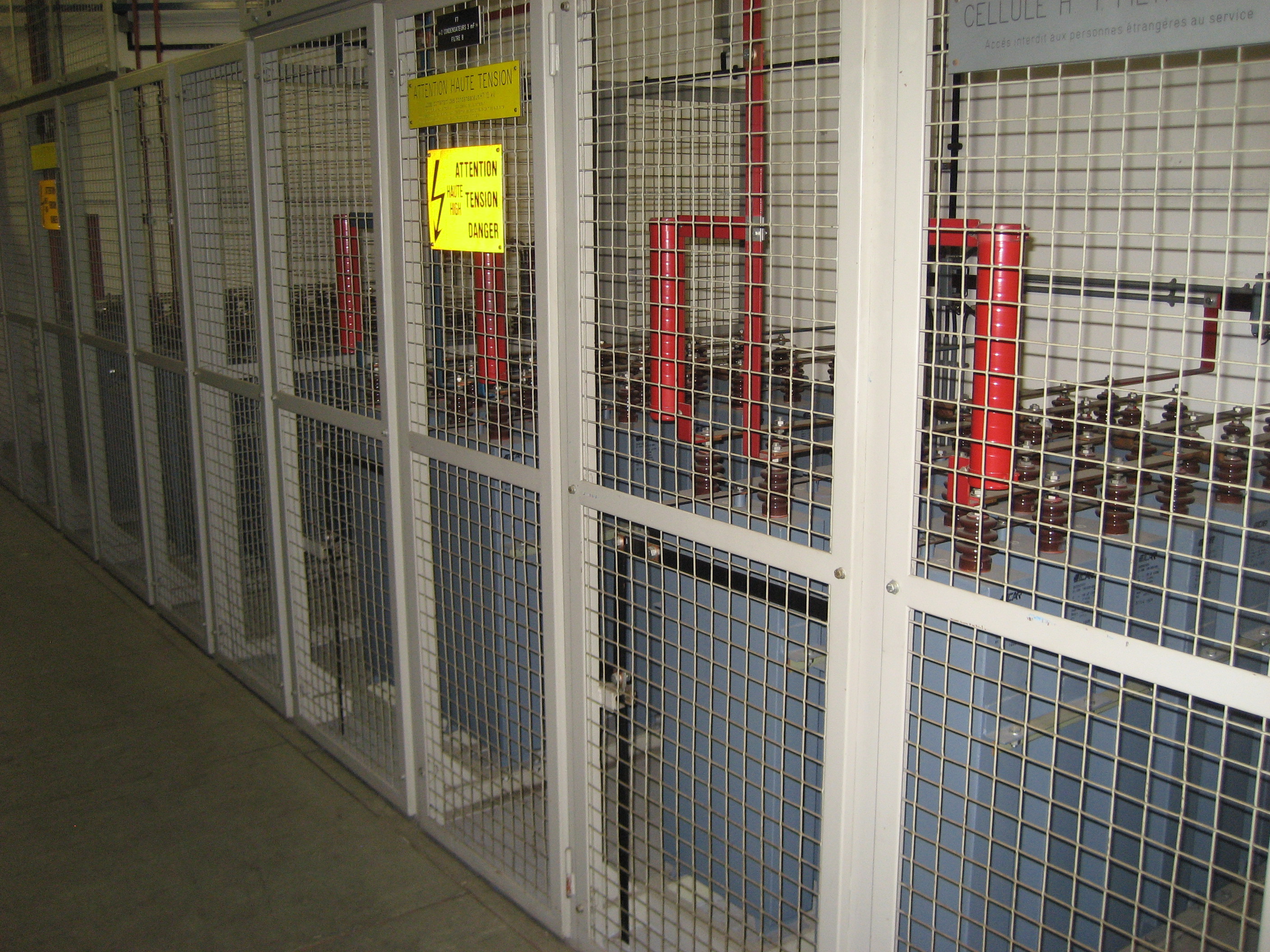
- 358 R-205: Filter RdC
- 358 R-401: Motor/Generator Set
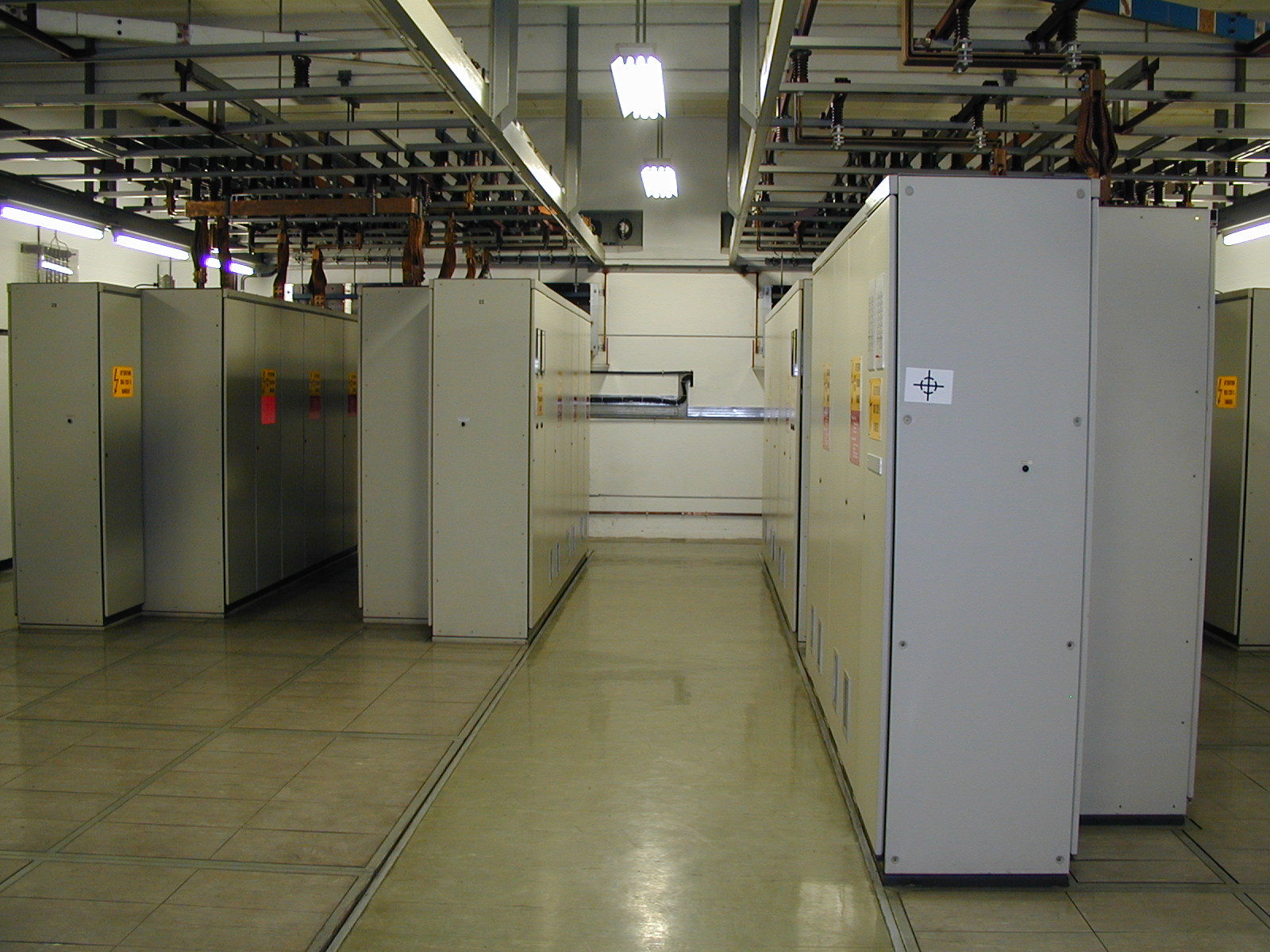
- 358 R-405: Thyristors Power converters room
- 358 1-412: Filter 1st Floor
- 358 1-414: Power Switch MPS/POPS
- 355 R-012: Magnet reference room (U101)
- 355 R-034: Electrical Sub-Station 6
Production Contract & Contract History
- Manufacturer: SIEMENS
- Production year: 1968